Checkline TI-CMXDLP User Manual
Page 41
– 41 –
7.0 USING THE DISPLAY OPTIONS
A key feature of the TI-CMXDLP is the ability to toggle between four different
display options; Digits, RF, RECT and B-Scan. All views provide a digital readout of
base material and coating thickness measurements, while also displaying the alarm
tolerances, if active. A key feature of the TI-CMXDLP is the waveform display.
The waveform is a graphical representation of the sound relections returning to the
transducer. Consider standing at the base of a canyon and screaming “Hello There”.
After a brief delay, you will here multiple echoes, “Hello There’s” repeated back to you.
The waveform display shows the amplitude of the signal received on the vertical(Y)
axis and time (shown in units of thickness) on the horizontal (X) axis. The waveform
display is very useful for viewing and adjusting the location of the gates. The gates
are typically used to eliminate potential surface noise by adjusting the starting point in
single echo modes, for multi echo measurement modes, as well as to adjust the threshold
(sensitivity) in either mode. The waveform display is also very useful for locating pits
and internal laws in materials.
The B-Scan display is also very useful when scanning surfaces and viewing the
cross section of the test material. It provides a convenient way of visually proiling,
or drawing a picture of, the blind surfaces during a scan. The B-Scan display is also
equipped with a scan bar representing the overall thickness. The scan bar gives the user
a visual indication when a law or defect passed over during the scan process. The scan
bar will delect off of the defect and return back to the overall thickness. Visually, this is
much easier to notice than watching for changes in the digital value displayed. The scan
bar has also been included in the large digits display mode for the same purpose.
NOTE: The following chapter outlines some of the ine adjustment features of the
TI-CMXDLP. The TI-CMXDLP has four different display options (RF A-Scan,
Rectiied A-Scan,B-Scan, and Large Digits). We’ll take a better look at these options in
this chapter.
NOTE: In order to recall and use the new adjustments made to the TI-CMXDLP at a
later time, the user must save the modiied settings in one of the setup locations prior to
powering off the unit. Refer section 12.0 for more information on setups.
– 64 –
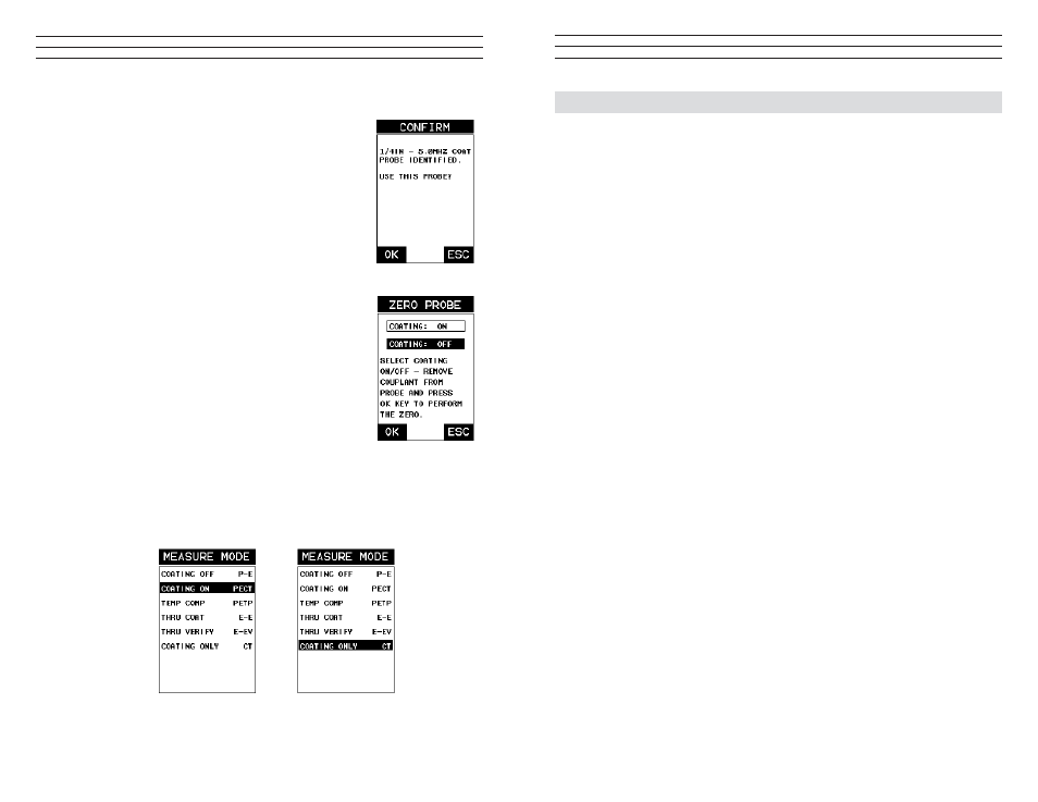
Probe Automatically Recognized (PECT only)
1. Press the OK key once to use the identiied probe, or
ESC to display a list of optional transducers.
NOTE: if the TI-CMXDLP recognizes a speciic transducer,
the user should always select OK to use the identiied probe.
The only time an alternative probe should be selected from a
list is if the user switched probes following initial power up
and recognition.
2. Assuming the TI-CMXDLP recognized the probe and
the OK key was pressed,the TI-CMXDLP will advance
to a Zero Probe menu. If the transducer was identiied
as a special transducer capable of measuring coating
thickness, a menu will be displayed allowing the user the
ability to toggle the coating thickness display on/off as
follows:
3. Press the UP and DOWN arrow keys to toggle the
coating option on/off.
Multi Mode Key Pressed (PECT & CT)
1. Press the MULTI MODE key located on bottom left of
the keypad to display the MEASURE MODE options
menu.
2. Press the UP and DOWN arrow keys to highlight the
COATING ON (PECT ) or COATING ONLY (CT) menu option
3. Press the ENTER key to enable the coating option, or ESC to cancel
changing the measure mode, and return to the main measurement screen.