Rockwell Automation Motion Analyzer Software User Manual
Page 92
92
Rockwell Automation Publication MOTION-UM004B-EN-P - October 2012
Chapter 2
Sizing Your System
If the gravity torque (Secondary Mass * 9.81 m/s
2
* Axis separation
2
) is known to
be small as compared to the acceleration torque or motor nominal torque, then it
may not be necessary to include the unbalanced mass effects.
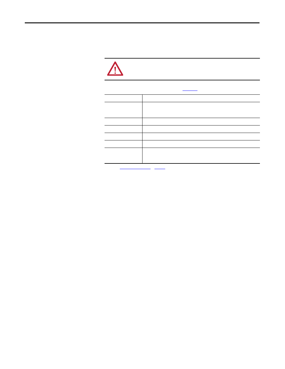
Table 54 - Unbalanced Load Parameters (refer to
)
ATTENTION: If the angle of movement in any profile segment is such that the
gravity torque changes significantly during that segment (a common
occurrence) then break the segment into smaller portions.
Parameter
Description
Primary Inertia
(1)
(1) Use the
to calculate the inertia value for your application, if the value is not readily
available.
The inertia of any balanced load about its own axis of rotation. For example, if the main
mass is a circular table which is driven about its own axis of symmetry, then Primary
Inertia is equal to the table inertia.
Losses
The losses consist of the torque lost in the system due to friction.
Secondary Inertia
The moment of inertia of the unbalanced mass about its own center of gravity.
Secondary Mass
The unbalanced mass.
Axis Separation
The distance between the secondary mass’ center of gravity and the axis of rotation.
Axis Angle
The starting angle of rotation. Zero indicates that at the start of the motion profile, the
center of gravity lies vertically below the center of rotation. This is the position of the load
if it is allowed to swing freely. Positive rotation is clockwise.