Rockwell Automation Motion Analyzer Software User Manual
Page 190
190
Rockwell Automation Publication MOTION-UM004B-EN-P - October 2012
Chapter 2
Sizing Your System
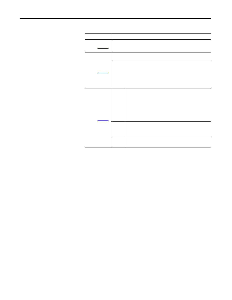
Table 110 - Linear Thruster Properties
Parameters
Description
Mechanism Data
(label 1 in
Figure 139
)
The Constant/Peak Load Mass, Constant/Peak Applied Force, and Stroke values are calculated
based on the parameters entered in the previous Load and Profile tabs and displayed here for
reference.
Orientation
(label 2 in
Figure 139
)
Only horizontal and vertical mounts are allowed, corresponding to 0 and 90° inclination in the
Load tab. Any other inclination in the Load tab is converted to horizontal mount.
Select the appropriate thruster orientation image for your application:
• Horizontal table base mounting
• Horizontal table side mounting
• Horizontal wall base mounting
• Horizontal wall side mounting
• Vertical wall base mounting
• Vertical wall side mounting
Configuration
(label 3 in
Figure 139
)
Overtravel
Length
This is the additional length of travel at each end of the motion profile to allow
for user-defined machine movements outside of the motion profile For
example, setup of a mechanism or tool change spacing. It also allows room for
the motor to stop if it accidentally exceeds the nominal travel envelope.
Switches (physical or software) detect this and the drive performs a controlled
stop. Click the Axis Stop tab to determine the minimum stopping distance
required. The value is added to both ends of the calculated motion profile travel
to make sure the proper length motor is specified and selected for the
application.
Actuator
Stroke
Length
From the Actuator Stroke pull-down menu, choose the required actuator stroke
length. If Automatic is chosen, the next largest value above Required Stroke +
(2 x Overtravel) is selected. Larger sizes may be selected if additional stroke
length is required for a function not considered in the motion profile.
Mounting
Surface
From the Mounting Surface pull-down menu, choose the type of surface the
thruster is mounted to.