Rockwell Automation Motion Analyzer Software User Manual
Page 185
Rockwell Automation Publication MOTION-UM004B-EN-P - October 2012
185
Sizing Your System
Chapter 2
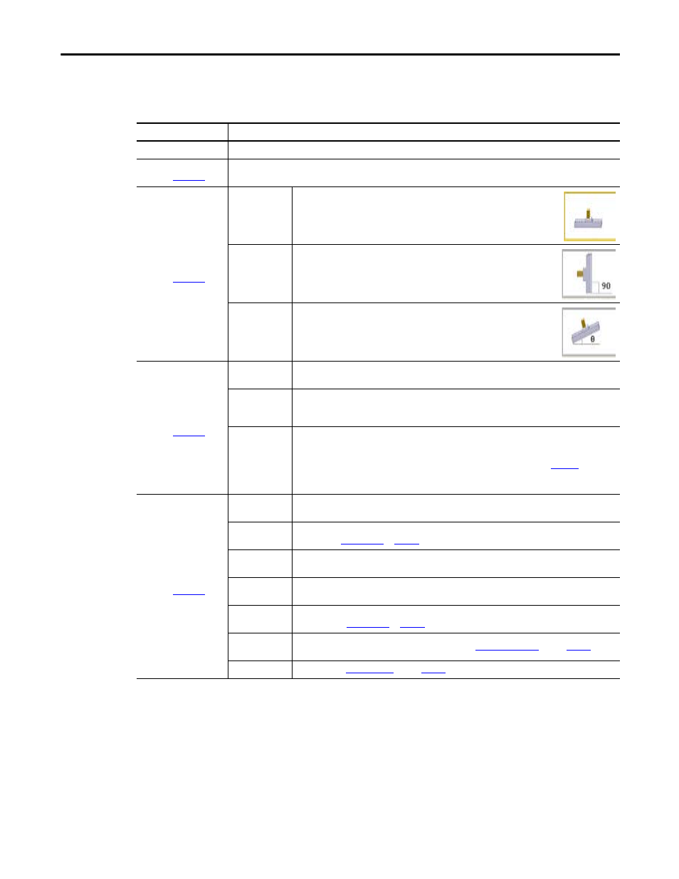
Enter the following parameters for linear motor mechanisms, if relevant.
Table 107 - Linear Motor Properties
Parameters
Description
Mechanism Type
From the pull-down menu, choose the mechanism type.
)
The Load, Stroke, Speed, and Acceleration values are calculated based on the parameters entered in the previous Load and
Profile tabs and displayed here for reference.
)
Horizontal
Relative motion between the two motor elements is directed horizontally.
Vertical
Relative motion between the two motor elements is directed vertically.
Custom
Relative motion between the two motor elements is directed at this angle relative to
the horizontal plane.
)
Ironless
Due to its non-cogging and low magnetic attraction characteristics, direct-drive ironless linear motors are
typically used for lighter duty bearings, smooth motion, and/or high precision applications.
Iron Core
At slightly lower cost relative to the Ironless configuration (one row of magnets versus two with ironless),
these high magnetic attraction motors are typically used with heavy-duty bearings to produce high
dynamic thrust performance.
Overtravel Length
The additional length of travel at each end of the motion profile to allow for user-defined machine
movements outside of the motion profile (for example, setup of a mechanism or tool change spacing). It
also provides room for the motor to stop if it accidentally exceeds the nominal travel envelope. Switches
(physical or software) detect this and the drive performs a controlled stop. Click the
determine the minimum stopping distance required. The value is added to both ends of the calculated
motion profile travel to make sure the proper length motor is specified and selected for the application.
Load and Application
(label 4 in
)
Carriage Mass
User input that specifies the mass of the moving carriage, including its support bearing pucks. This mass
should not include the mass of the moving motor elements.
Payload Mass
The constant mass of the moving parts of the load. This value does not include profile loads that are
entered in the
External Force
This represents any linear force that the motor must overcome (both during motion and while at rest). It
does not include frictional loads that are calculated elsewhere.
Heat Sink Type
From the Heat Sink Type pull-down menu, choose a heat sink type. The heat sink affects the motor
thermal continuous operation ratings.
Bearing Friction
Coefficient
The friction coefficient between the linear moving parts and the fixed parts of the system. You can edit
this value in the
Counter Balance
Type
From the Counter Balance Type pull-down menu, choose a
(refer to
Counter Balance
The mass of the
(refer to
).