Rigid coupling, Backlash – Rockwell Automation Motion Analyzer Software User Manual
Page 234
234
Rockwell Automation Publication MOTION-UM004B-EN-P - October 2012
Chapter 3
Understanding Your System Solution
3.2.2.4.1.1.1. Rigid Coupling
Rigid coupling occurs when the load is rigidly coupled to the motor.
Figure 171 - Rigid Coupling
Table 136 - Rigid Coupling Options
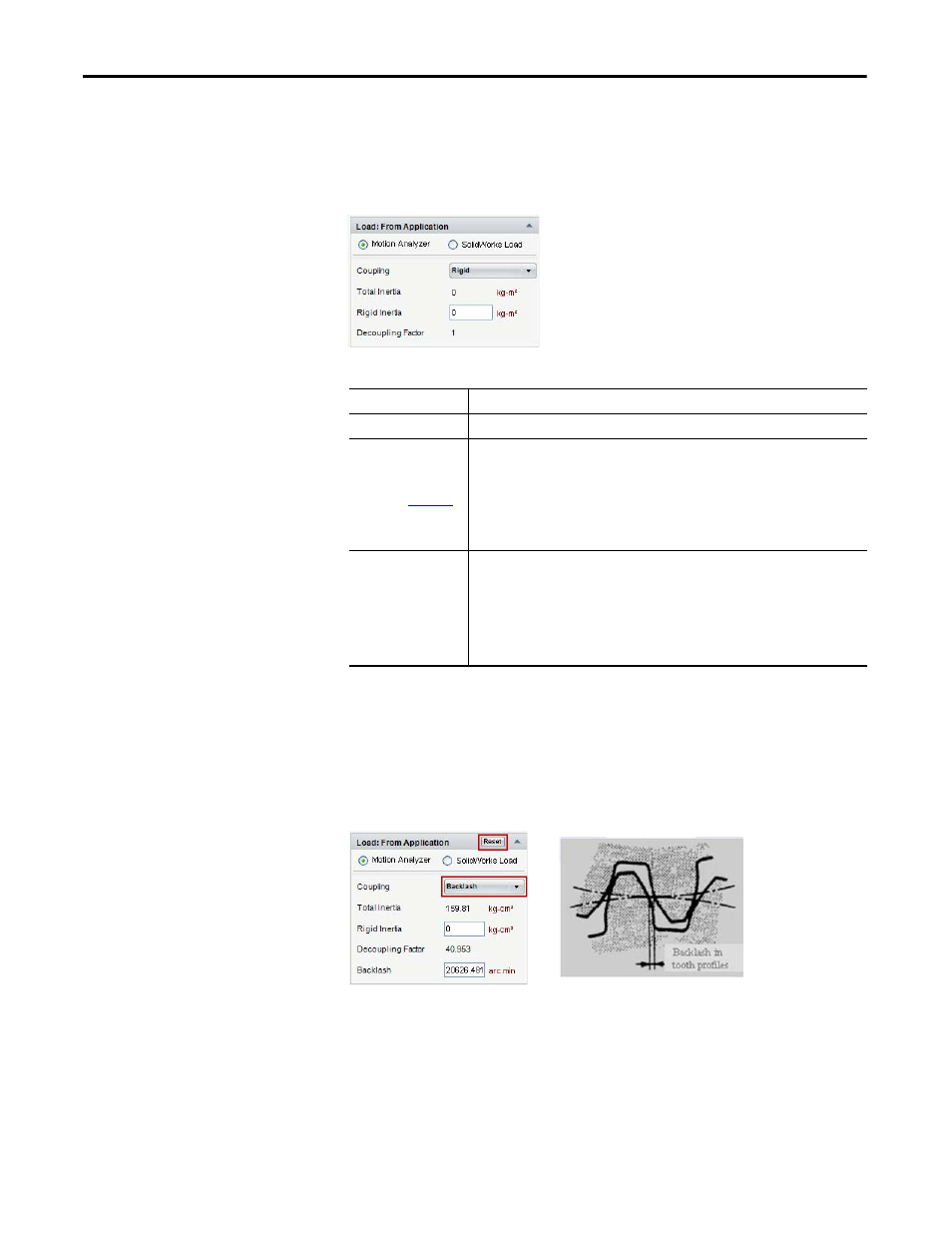
3.2.2.4.1.1.2. Backlash
Backlash occurs (for example) when a gearbox is added to the motor. Choosing
Backlash enables an additional field, in addition to the Rigid coupling fields,
where you can enter a backlash value.
Figure 172 - Backlash Coupling
Options
Description
Total Inertia
Maximum load inertia reflected to the motor shaft.
)
Any part of the load inertia that is rigidly attached to the motor shaft. This becomes
significant only when resonance or backlash is present because it becomes effectively part
of the motor. Any inertia entered here is subtracted from the Load inertia leaving the total
(system) inertia unchanged.
For example, a gearbox always has backlash, but its input shaft/pinion is normally coupled
rigidly to the motor shaft. This effectively becomes part of the motor, creating a higher
inertia motor. This can significantly alter the performance of an axis.
Decoupling Factor
This factor is much more indicative of potential dynamic performance than the
conventional Inertia Ratio. Velocity Bandwidth is increased by this factor when the load is
decoupled. Instability typically results beyond 2 unless gains are reduced. Anything greater
than 1 starts to impact performance.
DF = Jdc / (Jm + Jrc) + 1
Where, DF = Decoupling Factor, Jdc = decoupled load inertia,
Jm = motor inertia, Jrc = rigidly coupled load inertia