Dc sharing – Rockwell Automation Motion Analyzer Software User Manual
Page 52
52
Rockwell Automation Publication MOTION-UM004B-EN-P - October 2012
Chapter 1
Welcome to Motion Analyzer Software
1.2.2.4.4.1. DC Sharing
Use the DC Sharing configuration to group axes to share a common DC bus and
input AC supply (optional).
Table 32 - Power Supply/Accessories Tabs (refer to
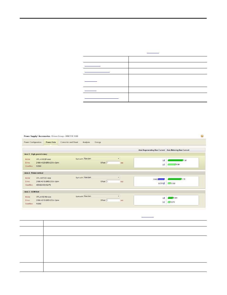
1.2.2.4.4.1.1. Power Data Tab
Click the Power Data tab to view regeneration and motoring data for each axis.
Figure 38 - Power Data Tab
Table 33 - Power Data Tab Properties (refer to
Parameters
Description
View regeneration and motoring data for each axis.
Select the shunts and capacitor for your system.
Analyze the drive module activity in terms of bus voltage and system
current. With this tab, you can also simulate changes to the system
parameters.
View input current values and energy savings estimates for each axis.
Configure Power Supply BOM Tab
Configure the bill of materials (BOM) for the power supply after fully sizing
the application.
Parameters
Description
Axis histograms
The axis histograms show a multi-axis representation of axis currents including peak motoring, average motoring, peak regenerating, and average
regenerating.
Random/Sync
relationship
The phase relationship between the various axis motion profiles in a common DC bus system affects the peak bus-current requirement. For example, if all axes
accelerate simultaneously (for example, synchronous operation), the bus current demand is much greater than if each accelerates in turn. The pull-down menu
lets you choose Random or Synchronized mode for axes operation. At least one axis should be set to random as the reference axis. Other axes may be set to
synchronized or random relative to the reference axis.
The safe setting for system sizing is all Random mode. In this case, the worst case current demand for each axis is automatically lined up by adjusting the phase
relationship of the axis motion profiles. If the phase relationship is known and will not change, the cycle profiles should be set up in the correct relationship and
appropriate synchronized set. This relationship is maintained by the system sizing algorithm and may result in a smaller drive being selected.
Offset
If all axis motion profiles are the same length and start at their correct respective positions at the default time, then the offsets will be zero. Otherwise, a
specified time offset may be used to align the motion profiles correctly.