Graph view – Rockwell Automation Motion Analyzer Software User Manual
Page 28
28
Rockwell Automation Publication MOTION-UM004B-EN-P - October 2012
Chapter 1
Welcome to Motion Analyzer Software
1.2.2.3.2. Graph View
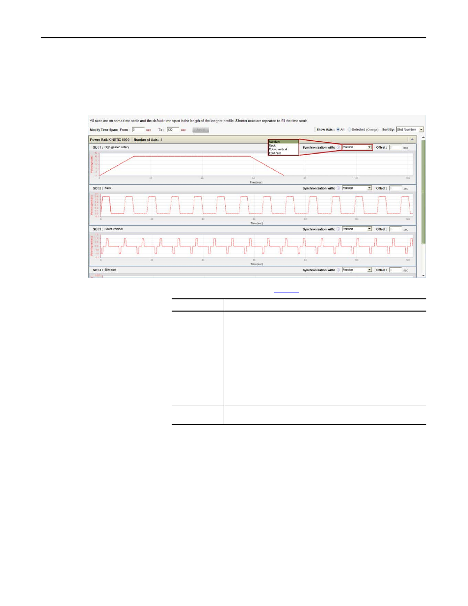
The Graph view displays profiles of all axes with the shorter profiles being
repeated to fit the length of the longest profile.
Figure 21 - Graph View Example
Table 14 - Graph View Options (refer to
Option
Description
Synchronized with
The phase relationship between the various axis profiles in a common DC bus system affects
the peak bus current requirement. For example, if all axes accelerate simultaneously, the bus
current demand is much greater than if each axis accelerates in turn.
From the Synchronized with pull-down menu, choose the random or synchronized operation
for each axis.
Set at least one axis to Random as the reference axis. Set other axes to be synchronized with
the reference axis or Random.
The safe setting for system sizing is all Random. In this case the worst case current demand for
each axis is automatically lined up by adjusting the phase relationship of the axis profiles.
If the phase relationship is known and will not change, the Cycle Profiles should be set up in
the correct relationship and Synchronized with set. This relationship is maintained by the
system sizing algorithm and may result in a smaller drive being selected.
Offset
If all axis profiles are the same length and start at their correct respective positions, then the
offsets will be zero. Otherwise, the offset may be used to align the profiles correctly.