Compute using inertia and ratio – Rockwell Automation Motion Analyzer Software User Manual
Page 193
Rockwell Automation Publication MOTION-UM004B-EN-P - October 2012
193
Sizing Your System
Chapter 2
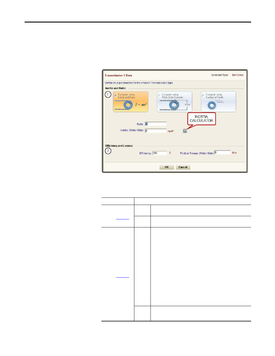
2.4.1. Compute Using Inertia and Ratio
Use this mode to directly enter the transmission component ratio and effective
inertia. This option is available for all transmission components.
Figure 142 - Compute Using Inertia and Ratio Dialog Box
Enter the following parameters for inertia and ratio, if relevant.
Table 113 - Compute Using Inertia and Ratio Properties
Parameters
Description
Inertia and Ratio
(label 1 in
)
Ratio
Transmission component ratio. If a straight-through coupling is being modeled,
set Ratio = 1.
Inertia
Inertia on the motor side (the rotor inertia and if a gearbox is present, the
inertia of the pinion attached to the rotor).
Efficiency and Losses
(label 2 in
)
Efficiency
Efficiency is widely misused. It refers to the ratio of output power to input
power for a single operating condition, but a servo system typically operates
over a wide range of operating conditions. A gearbox supplier normally
specifies the efficiency at an optimum point such as full load and full speed.
For example, a gearbox that has an output rating of 100 N•m (885 lb•in) and an
efficiency of 98%. This means that the losses at full load are 2 N•m (18 lb•in).
But because most of the losses in a gearbox are due to shaft seal friction and
churning of the lubricant, this would not reduce significantly at a lower load
torque.
In using this gearbox, a well-matched servo motor only has a continuous rating
around one third of the peak torque, and it is quite likely that the average
torque over the motion cycle would be even lower, for example about 20 N•m
(177 lb•in) at the gearbox output. The losses of 2 N•m (18 lb•in) amount to 10%
of the load on the motor, which can have a significant effect on the
temperature rise of the motor.
Motion Analyzer software overcomes this problem by dynamically computing
the real losses throughout the motion cycle, and thereby avoids
underestimating the effect of losses on the motor.
Friction
Torque
This is the torque caused by friction on the motor side between the rotor and
the transmission component. This value can be obtained from the supplier or
Engineering tables.