A.2.6 diameter calculator, A.2.7 flying splice unwinds – Rockwell Automation WebPak 3000 DC Drive Application Workbook Version 1.1 User Manual
Page 85
Using the WebPak 3000 Drive for Web Applications: The Basics
A-7
A.2.6 Diameter Calculator
The need for a diameter calculator function was established under the Type 2 field
current regulator design. However, the unwind and winder variable diameter
applications require instantaneous diameter information for the additional functions of
inertia compensation, taper tension, and control loop gain profiling.
The diameter calculator requires two signal inputs to perform its task. Web speed,
which is typically approximated by line speed reference, and motor speed are used to
calculate the running diameter as a software value, which is applied to modify the
drive system functions that have been programmed to be diameter sensitive.
The diameter calculator is capable of covering a maximum diameter range of 20:1.
Full roll diameter can be a maximum of 20 x core diameter up to a maximum of
120 inches.
A.2.7 Flying Splice Unwinds
The entry zone of a web process line can be either a single-position unwind drive or,
when the process is continuous, a two-position unwind drive with flying splice
operation. A flying splice two-position unwind is more complex then a single-position
winder due to the performance issues related to the splice sequence.
The individual unwind spindle drives have to support the steady state operation of
unwinding the web into the process under the primary tension control mode in addition
to accurately maintaining tension during the dynamics of the splice.
In some unwind flying splice machines, the need for a control function called “current
memory” may exist. This function changes the drive on the outgoing roll from its
primary tension regulator to a current regulator whose current reference is the
memorized value of its armature current just prior to being switched out of tension
operation.
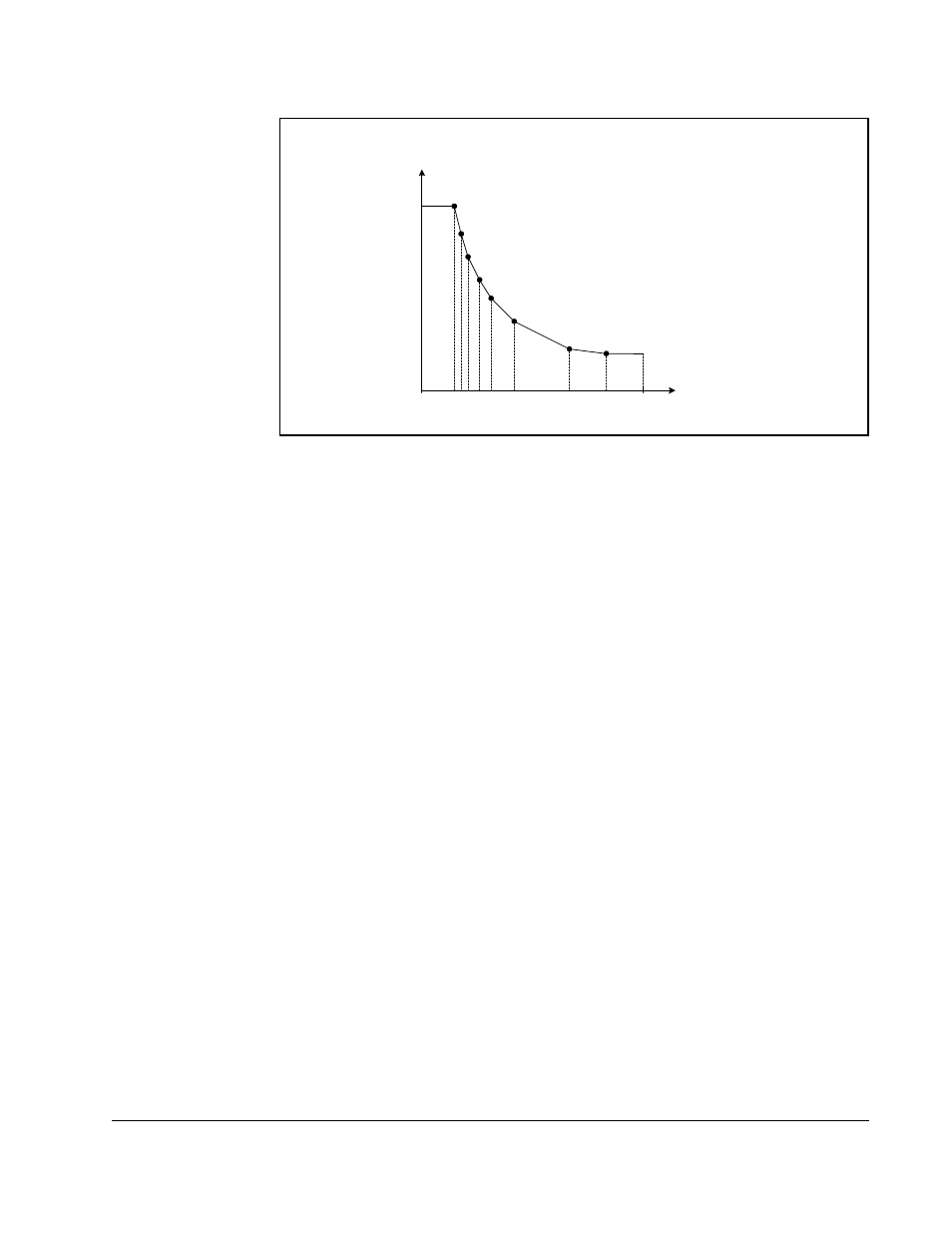
Figure A.1 – Typical Type 2 Field Reference Curve
F I E L D I N P U T n
Field
Current
1
2
3
4
5
6
7
8
Motor RPM or
Roll Diameter
FIELD CURRENT n
GEAR IN
SPEED
0