Configuring losses compensation, Hapter – Rockwell Automation WebPak 3000 DC Drive Application Workbook Version 1.1 User Manual
Page 49
Configuring Losses Compensation
8-1
C
HAPTER
8
Configuring Losses Compensation
When a current regulator is used to control tension or to support load share profiling,
its performance will be enhanced by the application of friction and windage loss
compensation. These losses vary with line speed/motor speed; therefore,
FRICTION
LOSS
(P.123) and
WINDAGE
LOSS
(P.243), which are set based on machine dynamics
such as bearing loads and gearbox loads, will be modified as a function of speed.
Line speed is normalized by applying
SPD
SOURCE
SELECT
OUT
(P.193) and
TOP
LINE
SPEED
(P.020) to a multiplier block. The block output is multiplied by
NORM
ROLL
DIA
(P.131) to convert it to a rotational speed.
The speed-modified values of P.123 and P.243 are scaled, summed and set
proportional to motor field amps based on the value of
NORM
FIELD
REF
(P.130).
This composite signal is identified as
LOSSES
COMPENSATION
(P.316). Refer to figure
A.15 in Appendix A of the software manual (D2-3444) as you configure losses
compensation.
þ
To configure the losses compensation function:
▲
Set
FRICTION
LOSS
(P.123).
▲
Set
WINDAGE
LOSS
(P.243).
þ
To calibrate the losses compensation function:
▲
Tune the speed loop with its connected load. If the load is variable diameter,
use empty core diameter.
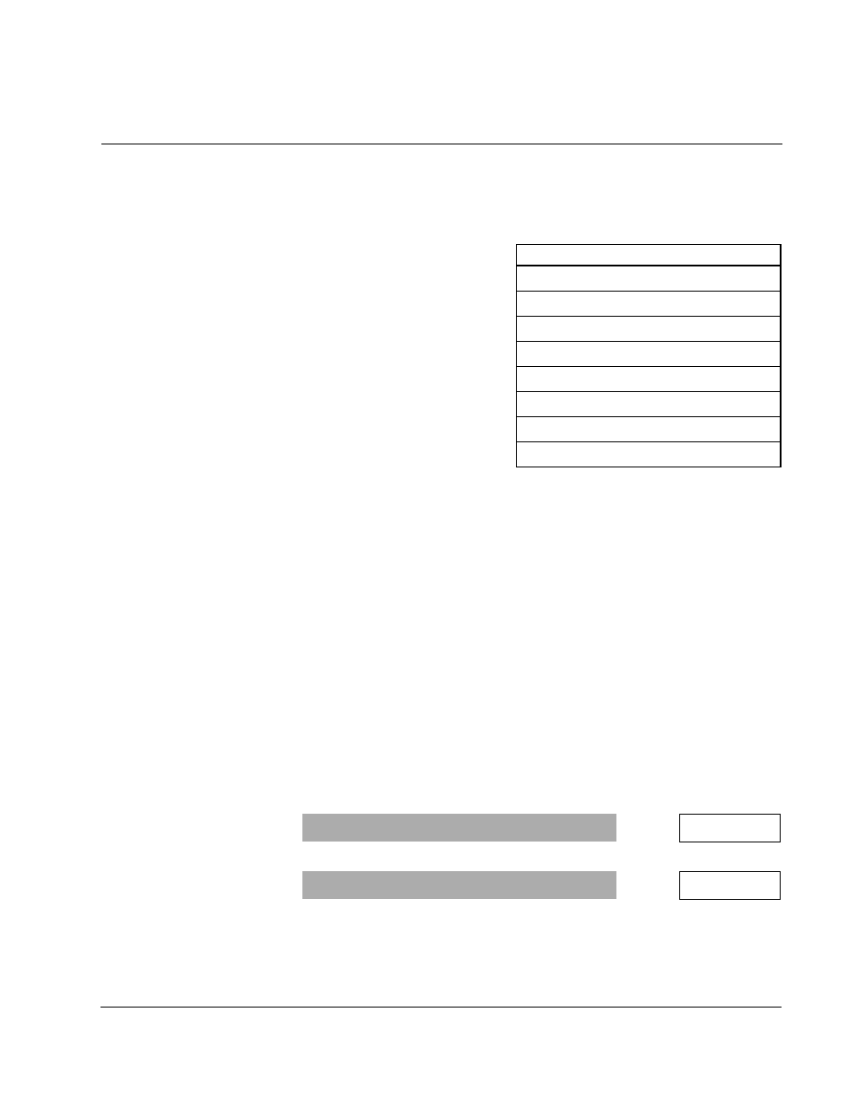
Use This Chapter for These Applications:
•
Constant Diameter Speed Regulator
•
Variable Diameter Speed Regulator
•
Constant Diameter Current Regulator
•
Variable Diameter Current Regulator
•
Variable Diameter Position Regulator
•
Constant Diameter Tension Regulator
•
Variable Diameter Tension Regulator
•
Generic
Range: 0.0 to 50.0%
P.123 =
%
Range: 0.0 to 50.0%
P.243 =
%