The diameter calculator, 2 the diameter calculator – Rockwell Automation WebPak 3000 DC Drive Application Workbook Version 1.1 User Manual
Page 42
6-2
WebPak 3000 DC Drive Application Workbook, Version 1.1
▲
Set
DIAMETER
UPDATE
RATE
(P.867) to specify the number of roll revolutions
between diameter updates. This is based on web thickness. Typically, thinner
webs use a higher update number.
þ
For variable diameter applications (unwinds or winders),
GEAR
IN
SPEED
(P.011) is the motor speed at
TOP
LINE
SPEED
(P.020) and
EMPTY
CORE
DIAMETER
(P.830):
▲
Set
EMPTY
CORE
DIAMETER
(P.830).
6.2
The Diameter Calculator
Six of the inputs to the diameter calculator function block are calculated by the system:
•
The absolute value of
SPEED
RAMP
OUTPUT
(P.199).
•
The absolute value of
SPD
LOOP
FEEDBACK
(P.296).
•
The output of the threshold function block.
•
A reset diameter value determined by the status of digital input
DIAMETER
SELECT
A
TP
(P.495) (terminal 59 on the I/O Expansion board) and digital input
DIAMETER
SELECT
B
TP
(P.496) (terminal 60 on the I/O Expansion board) as shown in the
following table. P.495 and P.496 can also be asserted over the network when a
network card is installed.
•
DIAMETER
/
TAPER
IN
TP
(P.192), which is the value in counts of the input after gain and
zero have been applied.
•
DIAMETER
RESET
TP
(P.829) will reset the diameter calculator to a diameter based on
the status of
DIAMETER
SELECT
A
TP
(P.495) and
DIAMETER
SELECT
B
TP
(P.496). P.829
is on when digital input 62 on the I/O Expansion board is on provided that
DIAMETER
RST
DIN
TP
(P.497) is asserted.
Range: 1 to 10
REVOLUTIONS
P.867 =
REV
Range: 1.00 to 30.00
INCHES
P.830 =
INCHES
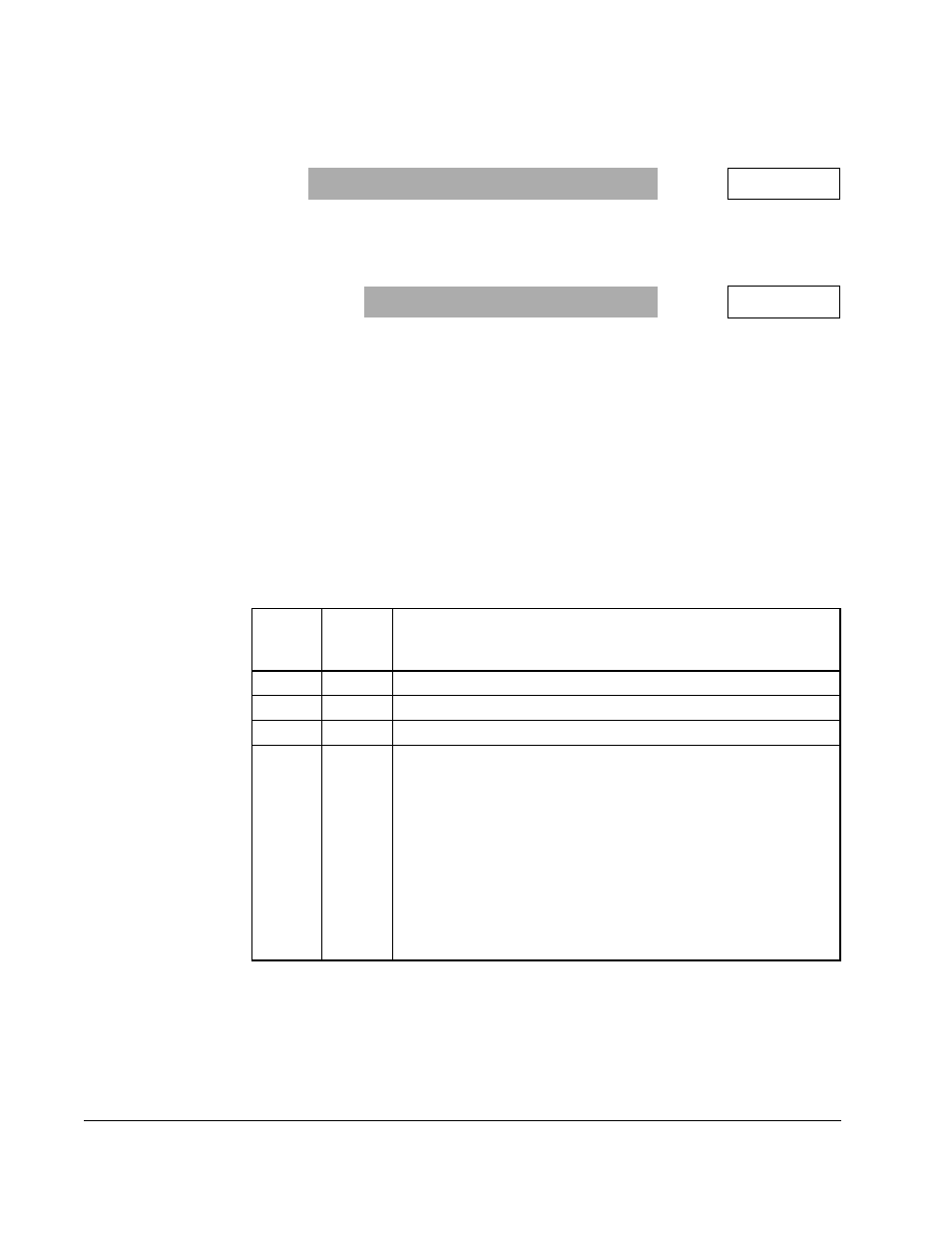
Status
Input A
(P.495)
Status
Input B
(P.496)
Reset Diameter Value
ON
OFF
WINDER
CORE
DIA
1 (P.822)
OFF
ON
WINDER
CORE
DIA
2 (P.824)
ON
ON
WINDER
CORE
DIA
3 (P.825)
OFF
OFF
UNWIND
DIAMETER
IN
(P.828) which is the analog signal of the
analog input diameter/taper (terminals 16, 17, and 18 on the
Regulator board) when
DIAMETER
/
TAPER
SELECT
(P.870) is set to
DIAMETER
.
Important: Note that the analog signal will be maximum at
core diameter and minimum at full roll diameter.
This is consistent with the output characteristics of
a sonic roll diameter detector. When a
potentiometer is used to set diameter, the
connections should reflect maximum volts at core
and minimum volts at full roll.