Rockwell Automation WebPak 3000 DC Drive Application Workbook Version 1.1 User Manual
Page 21
Configuring the Speed Loop
3-11
þ
To select the outer control loop proportional trim operation:
The value of the outer control loop
PI
limits is set proportional to the absolute value
of
SPEED
RAMP
OUTPUT
(P.199). This keeps the gain of the outer control loop
constant at all line speed operating levels.
A
SCALE
block is used to establish the range of the outer control loop percent
control. The output of the
SCALE
block will be a number that will change linearly
from the value of
OCL
PROP
TRIM
GAIN
(P.812) to 1.0 as
SPEED
RAMP
OUTPUT
(P.199)
changes from its minimum value of zero to
TOP
LINE
SPEED
(P.020).
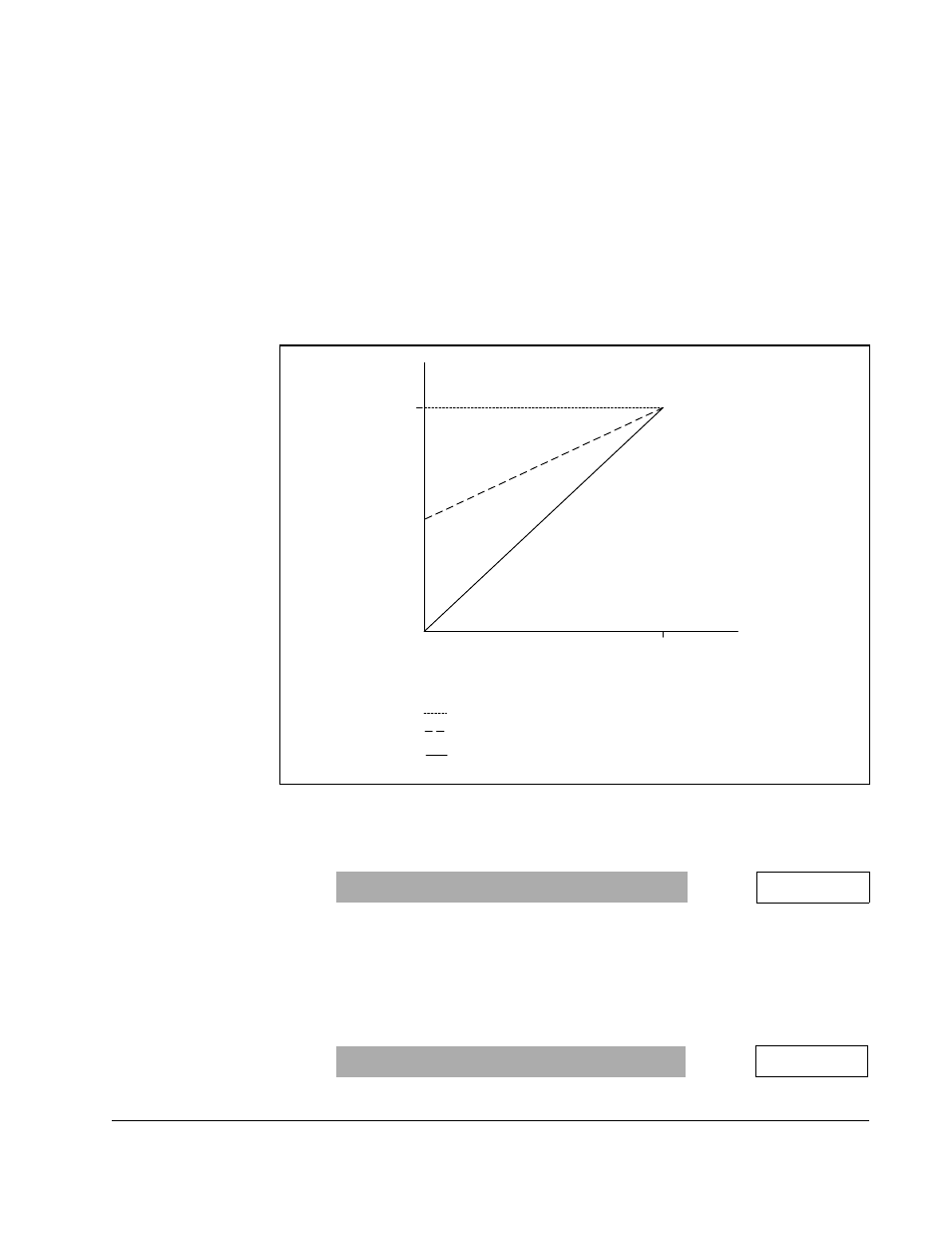
When P.812 is set at its default value of 1.0, the outer control loop
PI
limit will be a
fixed percentage of
TOP
LINE
SPEED
(P.020); but as line speed is decreased, the
limit will increase proportionately as shown in figure 3.1.
▲
Set
OCL
PROP
TRIM
GAIN
(P.812). The minimum value of P.812 should be set at
0.05 so that a minimum speed loop reference is available for stall tension
operation.
▲
Set
OCL
INVERT
ENABLE
(P.815) to specify the polarity of the outer control loop.
The location of a drive’s outer loop control zone in a process line may be
upstream or downstream of the lead section; therefore, the polarity of the
outer control loop needs to be set accordingly.
ENABLE
: The
OCL
signal is subtracted from the speed loop reference.
DISABLE
: The
OCL
signal is added to the speed loop reference.
Figure 3.1 – Outer Control Loop Proportional Trim
Range: 0 to 1.000
P.812 =
Range:
ENABLE
,
DISABLE
P.815 =
O u t e r L o o p
PI Limit
S p e e d
O C L
P R O P
T R I M
G A I N
(P.812) = 1.0
O C L
P R O P
T R I M
G A I N
(P.812) >0.0<1.0
O C L
P R O P
T R I M
G A I N
(P.812) = 0.0
Curve 1
1
2
3
M a x i m u m P I
Limit
T o p L i n e S p e e d
Curve 2
Curve 3