Speed loop regulator with gain profiling, 5 speed loop regulator with gain profiling – Rockwell Automation WebPak 3000 DC Drive Application Workbook Version 1.1 User Manual
Page 24
3-14
WebPak 3000 DC Drive Application Workbook, Version 1.1
▲
Set
SPD
LEADLAG
SELECT
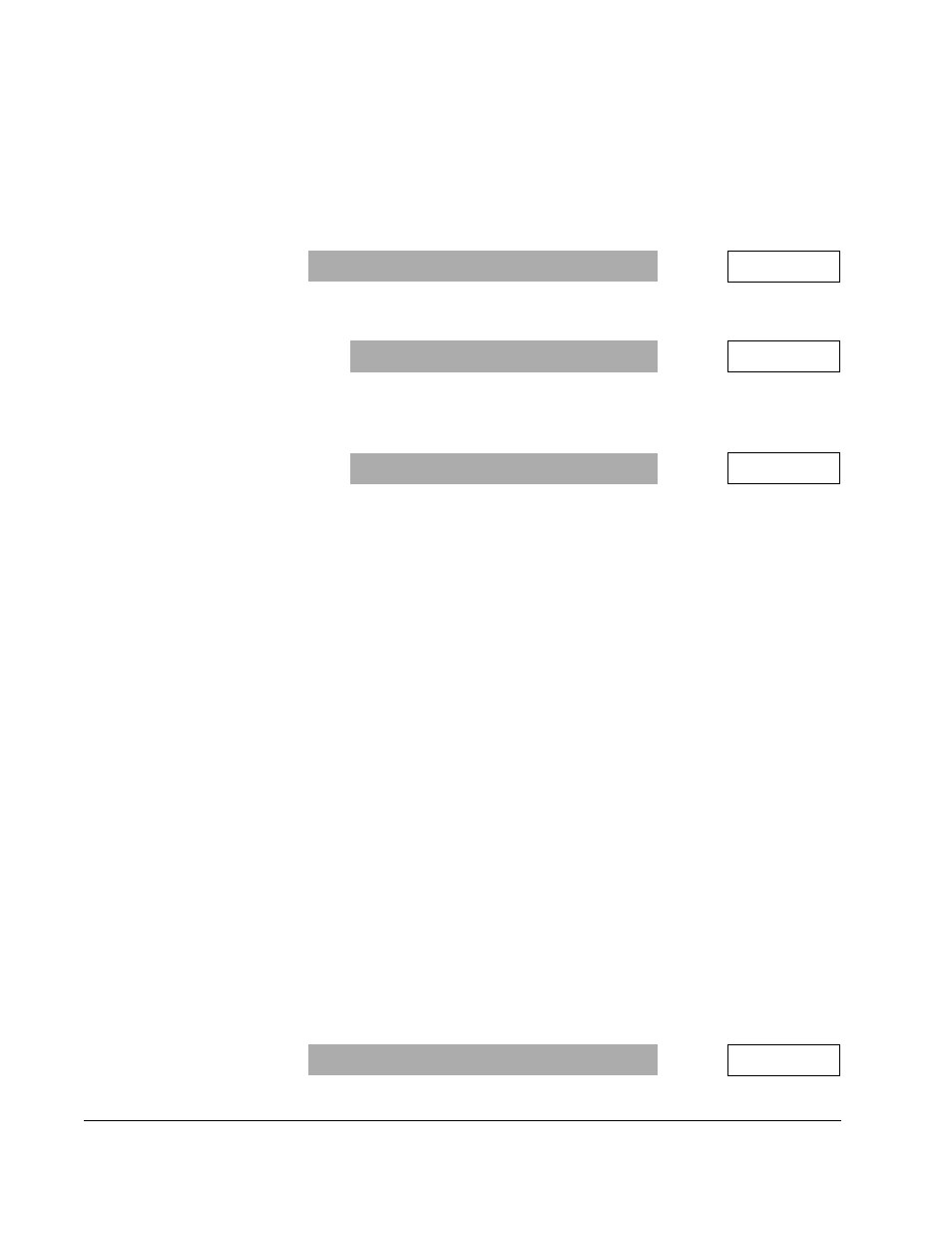
(P.216) to compensate for backlash in the drive-train
gears and couplings. The choices are:
LEAD
/
LAG
-
SPD
LEADLAG
LOW
FREQ
(P.214) specifies the lag break frequency.
BYPASS
- The lead/lag block is bypassed and the feedback signal is used
directly by the speed loop summing junction.
LAG
/
LEAD
-
SPD
LEADLAG
LOW
FREQ
(P.214) specifies the lead break frequency.
þ
If
SPD
LEADLAG
SELECT
(P.216) =
LEAD
/
LAG
or
LAG
/
LEAD
:
▲
Set
SPD
LEADLAG
LOW
FREQ
(P.214).
▲
Set
SPD
LEADLAG
RATIO
(P.213) to specify the ratio between the low and
high break frequencies. The selection of the high and low break
frequencies is dependent on the mechanical characteristics of the drive
train.
3.5
Speed Loop Regulator With Gain Profiling
Refer to figure A.7 in Appendix A of the software manual (D2-3444) as you configure
the speed loop regulator with gain profiling.
Output parameters
FIELD
REFERENCE
(P.590) and
INSTANTANEOUS
INERTIA
(P.230) are
inputs to the gain profiler block. They both have dynamic values that are calculated by
the field shaping and inertia calculator tasks, respectively.
The gain profiler calculates and outputs to the speed loop
PI
amplifier values for the
proportional gain (
KP
) and the integral gain (
WLD
).
The third gain profiler output is
SPEED
CROSS
OVER
(P.133), which is used as an input
to the position and current major outer control loop gain profilers.
The last gain profiler output is
SPD
LOOP
LAG
FREQ
(P.215), which provides a low pass
frequency filter at the output of the speed loop
PI
block. A positive or negative step
input to the
LAG
block drives the output to increase or decrease its value with respect
to the input. A lower lag frequency will exhibit a slower step response than a higher
one.
þ
To configure gain profiling:
▲
Set
SPEED
PROFILER
ENABLE
(P.127). The choices are:
ENABLE
- Use for all variable diameter applications. The profiler block uses
equations that are based on the dynamic physical properties of connected
load; therefore, a robust speed regulator that maximizes system response and
stability can be expected.
DISABLE
- Use for all constant diameter applications.
Range:
LEAD
/
LAG
,
BYPASS
,
LAG
/
LEAD
P.216 =
Range: 0.01 to 34.90
RAD
/
S
or 0.01 to 69.81
RAD
/
S
P.214 =
RAD
/
S
Range: 2 to 20
P.213 =
Range:
ENABLE
,
DISABLE
P.127 =