Figure 2-19. figure 2-20 – AT&T System 25 User Manual
Page 78
INSTALLATION
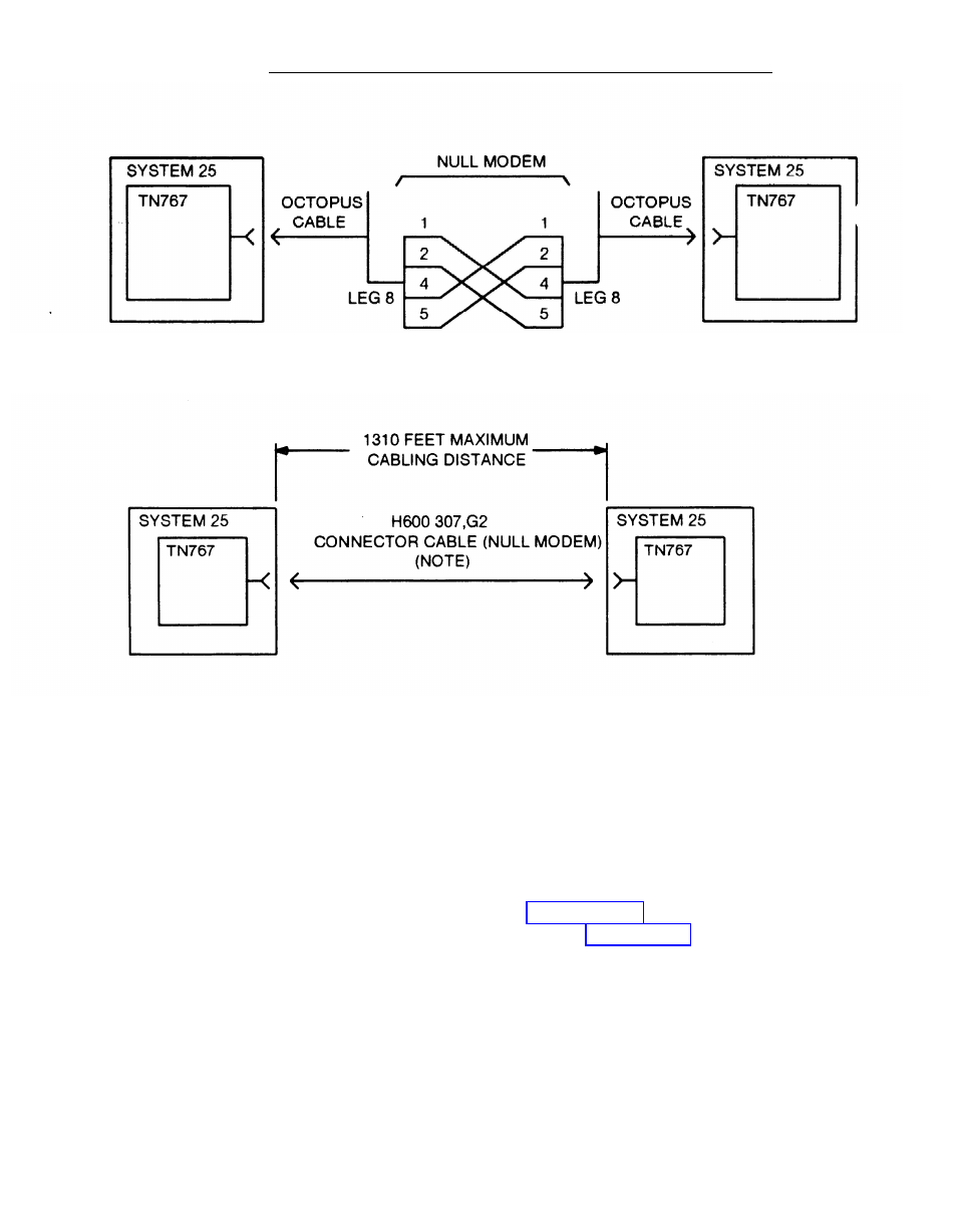
Figure 2-19.
Direct Connection (Side by Side)
NOTE: FOR DISTANCES OVER 50 FEET (15.2 M)
USE C6E CONNECTOR CABLE(S) BETWEEN
H600 307,G2 CONNECTOR CABLE AND DS1
TRUNK CIRCUIT PACK.
Figure 2-20.
Direction Connection (Side by Side)
Connections Between 1311 and 4310 Feet
For distances between 1311 and 4310 feet, CSUs equipped with Office repeaters
must be used to regenerate the DS1 signal. See “Install CSU” section of this
manual for the installation instructions for the CSU. Figure 2-21 shows a
functional diagram of this connection. If the connection is being made between
the S25 and a DEFINITY G1 or G2, System 75, or System 85, refer to the
System 85 Installation Manual (555-1 03-104) or the DEFINITY G1 Wiring Guide
(555-201-1 11) or the System 75 Wiring Guide (555-200-111) for the connecting
information.
2-54
- CL2909 (49 pages)
- 8434 (54 pages)
- 8434 (38 pages)
- TL74358 (41 pages)
- Definity 7410 (31 pages)
- 8503T (33 pages)
- NORTEL BCM50 (37 pages)
- EL52309 (8 pages)
- 100 (6 pages)
- 135 (8 pages)
- ML17959 (82 pages)
- System 75 (10 pages)
- CL82409 (9 pages)
- 2300 (13 pages)
- CL82601 (2 pages)
- CL82351 (2 pages)
- CL82351 (2 pages)
- TL74258 (97 pages)
- 820 (6 pages)
- 1856 (7 pages)
- 1187 (48 pages)
- 972 (29 pages)
- TR1909 (12 pages)
- TRIMLINE 210M (2 pages)
- SB67158 (2 pages)
- E2115 (27 pages)
- Generic 2 (44 pages)
- SBC-420 (26 pages)
- Partner Plus (26 pages)
- 1080 (18 pages)
- 1040 (74 pages)
- RIM BlackBerry Bold MDC 9000 (35 pages)
- System 25 (85 pages)
- System 25 (35 pages)
- System 25 (75 pages)
- DECT CL84209 (12 pages)
- DEFINITY 8101 (4 pages)
- TRIMLINE TR1909 (43 pages)
- 902 (6 pages)
- TL74108 (8 pages)
- 7406BIS (72 pages)
- CL4939 (77 pages)
- PARTNER MLS-12 (5 pages)
- 952 (8 pages)