Z| accuracy chart – GW Instek LCR-8000G Series User Manual
Page 67
APPENDIX
133
133
133
133
≦10 kHz O/S Trimming Point List
The frequency of the extra trimming point is the measurement
frequency you were using before entering the calibration mode.
“O/S Trim Error!” warning will still appear after running a
≦10
kHz trimming if you choose to use a measuring frequency higher
than 10 kHz or other than where you were when you ran the
≦10
kHz trimming.
LCR Models
LCR-8101G
LCR-8105G
LCR-8110G
Trimming Point
7 points
7 points
7 points
1
20 Hz
20 Hz
20 Hz
2
100 Hz
100 Hz
100 Hz
3
300 Hz
300 Hz
300 Hz
4
1 kHz
1 kHz
1 kHz
5
3.3 kHz
3.3 kHz
3.3 kHz
6
10 kHz
10 kHz
10 kHz
7
Extra Trimming
Point
Extra Trimming
Point
Extra Trimming
Point
Spot Frequency O/S Trimming Point’s List
There is no extra trimming point if you choose to use Spot Freq. O/S
trimming.
“O/S Trim Error!” warning will still appear after running a spot
frequency trimming if you choose to use a measuring frequency
other than where you were when you ran the spot frequency O/S
trimming.
LCR Models
LCR-8101G
LCR-8105G
LCR-8110G
Trimming Point
1 point
1 point
1 point
1
The frequency of the sole trimming point is the
very measuring frequency you were using before
entering the calibration mode.
LCR-8000G Series User Manual
134
134
134
134
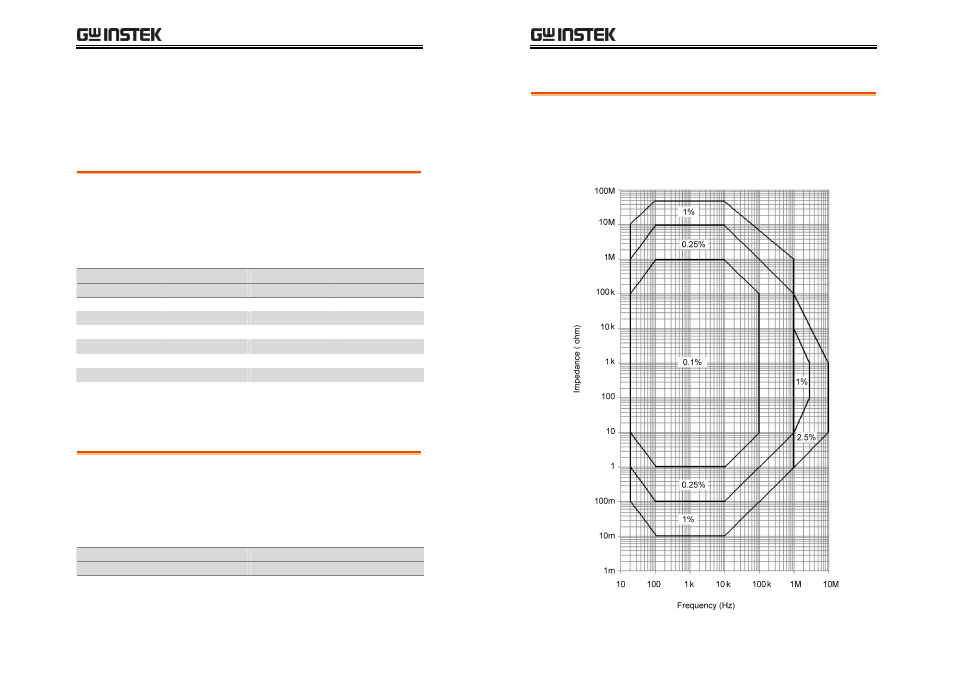
|Z| Accuracy Chart
Over the available frequency bands, the |Z| Accuracy Chart defines
the measurement ranges available at specified accuracies. All curves
assume that Slow measurement speed is used, that the analyzer has
been trimmed at the frequency and level used for measurements,
the factory calibration is valid and that the component under test is
pure.