Measurement item description – GW Instek LCR-8000G Series User Manual
Page 19
BASIC MEASUREMENT
37
37
37
37
Measurement Item Description
In general, two items, primary and secondary, are combined in a
single measurement. The following table shows the available
combinations. Overview of each measurement item is listed from
the next page.
Measurement combination
:Available,
:Not available, :Combination doesn’t exist.
1st measurement
2nd measurement
Circuit model Graph *Prog
Q D R
AC
G Angle Series Parallel
Capacitance (C)
Inductance (L)
Reactance (X)
Susceptance (B)
Impedance (Z)
Admittance (Y)
DC Resistance(R
DC
)
Quality factor (Q)
Dissipation factor (D)
AC Resistance (R
AC
)
Conductance (G)
Angle (θ)
*Prog: Multi-step program
•
The graph measurement is described in the Graph Mode chapter,
page87.
•
The multi-step program mode is described in the Pass/Fail test
chapter, page70.
LCR-8000G Series User Manual
38
38
38
38
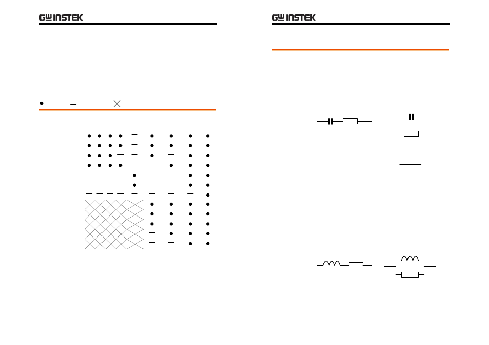
Series/Parallel circuit models
Background
For measuring AC Resistance, Capacitance,
Reactance, Inductance, and Susceptance, series and
parallel equivalent circuit models are available.
Select the model according to the component
value.
Capacitance (C) Series diagram
Parallel diagram
Series formula
(
)
2
1
D
C
C
P
S
+
=
D=dissipation factor
Parallel formula
(
)
2
1
D
C
C
S
P
+
=
D=dissipation factor
When to use Series (C
S
)
Small capacitance:
Reactance (X
C
) < 1kΩ
Note:
fC
X
C
π
2
1
=
When to use Parallel (C
P
)
Large capacitance:
Reactance (X
C
) > 1kΩ
Note:
fC
X
C
π
2
1
=
Inductance (L)
Series diagram
Parallel diagram