GW Instek LCR-8000G Series User Manual
Page 55
REMOTE CONTROL
109
109
109
109
Configure GPIB interface
Connection
Connect the GPIB cable to the
rear panel port: 24-pin female
connector.
Pin assignment
12
1
24
13
Pin1 Data line 1
Pin13 Data line 5
Pin2 Data line 2
Pin14 Data line 6
Pin3 Data line 3
Pin15 Data line 7
Pin4 Data line 4
Pin16 Data line 8
Pin5 EOI
Pin17 REN
Pin6 DAV
Pin18 Ground
Pin7 NRFD
Pin19 Ground
Pin8 NDAC
Pin20 Ground
Pin9 IFC
Pin21 Ground
Pin10 SRQ
Pin22 Ground
Pin11 ATN
Pin23 Ground
Pin12 Shield (screen)
Pin24 Signal ground
GPIB constraints
•
Maximum 15 devices altogether, 20m cable
length, 2m between each device
•
Unique address assigned to each device
•
At least 2/3 of the devices turned On
•
No loop or parallel connection
LCR-8000G Series User Manual
110
110
110
110
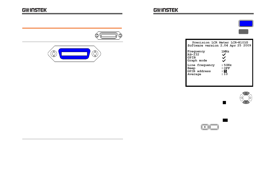
Select GPIB
address
1. Press the Menu key and F5 (System).
The system configuration appears.
Menu
F 5
2. Press the Up/Down key and move
the cursor to GPIB.
5
GPIB address
:
3. Use the numerical keys to enter the GPIB
address, 1 ~ 30.
30
GPIB address
:
Address 5
Enter
- GDB-03 (99 pages)
- GLA-1000 Series User Manual (111 pages)
- GLA-1000 Series Quick start guide (20 pages)
- GOS-630FC (20 pages)
- GOS-635G (36 pages)
- GOS-6000 Series (27 pages)
- GOS-6103C (30 pages)
- GOS-6100 Series (30 pages)
- GRS-6000A Series (51 pages)
- GDS-122 Installation Guide (4 pages)
- GDS-122 User Manual (52 pages)
- GDS-2000A series CAN/LIN bus User Manual (18 pages)
- GDS-2000A series Quick start guide for DS2-FGN (6 pages)
- GDS-2000A series Freewave User Manual (26 pages)
- GDS-2000A series Quick start guide for Logic analyzer option (18 pages)
- GDS-2000A series Quick start quide for DS2-LAN (2 pages)
- GDS-2000A series Option User Manual (80 pages)
- GDS-2000A series User Manual (261 pages)
- GDS-2000A series Programming Manual (272 pages)
- GDS-2000A series Single sheet for LA Quick start guide (2 pages)
- GBS-1000 Series Programming Manual (88 pages)
- GBS-1000 Series User Manual (187 pages)
- GDS-1000-U Series firmware upgrade (1 page)
- GDS-1000-U Series Programming Manual (70 pages)
- GDS-1000-U Series Quick start guide (2 pages)
- GDS-1000-U Series User Manual (133 pages)
- GDS-1000A-U Series Programming Manual (88 pages)
- GDS-1000A-U Series Quick start guide (2 pages)
- GDS-1000A-U Series User Manual (148 pages)
- GDS-3000 Series GCP-530/1030 current probe User Manual (40 pages)
- GDS-3000 Series GDP-025/050/100 differential probe User Manual (21 pages)
- GDS-3000 Series DS3-PWR Power analysis manual (37 pages)
- GDS-3000 Series User Manual (209 pages)
- GDS-3000 Series Programming Manual (103 pages)
- GDS-3000 Series DS3-SBD Serial Bus decode (29 pages)
- GDS-3000 Series GKT-100 deskew fixture User Manual (1 page)
- GDS-3000 Series GUG-001, GPIB to USB adapter User Manual (15 pages)
- GDS-300 Series User Manual (188 pages)
- GDS-300 Series Programming Manual (139 pages)
- GDS-300 Series Quick start guide (21 pages)
- GRF-3300 Series Student Manual (26 pages)
- GRF-3300 Series Teacher Manual (26 pages)
- GRF-1300A (124 pages)
- GSP-810 User Manual (40 pages)
- GSP-810 Software Manual (3 pages)