Wiring the four-wire rtd resistance input modules, Wiring the strain input modules, One-gauge method – Yokogawa PC-Based MX100 User Manual
Page 57
2-12
IM MX100-01E
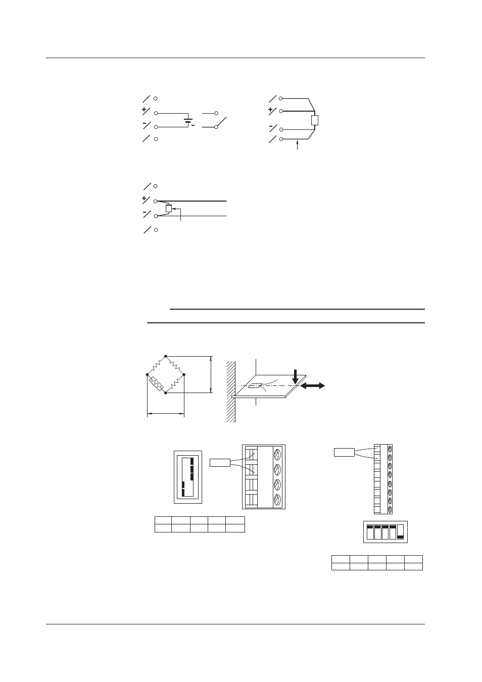
Wiring the Four-Wire RTD Resistance Input Modules
A
B
I
C
Resistance, RTD
Resistance per lead wire of 10 Ω or less
A
B
I
C
Voltage
Nothing connected to the
I or C terminal
+
DC voltage
Input
Contact
DC current input
Shunt resistor
Example: For 4 to 20 mA input,
shunt resistance values should
be 250
Ω ±
0.1%.
–
+
C
I
A
B
• DC voltage input/DI (contact) input
• RTD input, resistance input
• DC current input
Terminal type:
Clamp
Applicable wire size: 0.14 to 1.5mm
2
(AWG26 to 16)
Wiring the Strain Input Modules
Note
When using a sensor without a remote sensing wire, use the DV450-001 (conversion cable).
•
One-Gauge Method
Setting switch
ON
OFF
No.1
No.2
No.3
No.4
No.5
A(+V)
B( L)
C(-V)
D( H)
-B12, -B35
E
e
Rg
R
R
R
Rg
No.1
ON
No.2
ON
No.3
ON
No.4
OFF
No.5
OFF
Rg
R: fixed resistance
r: resistance value of lead
wire
Rg: resistance value of strain
gauge
e: output voltage from bridge
E: voltage applied to bridge
Setting switch
-NDI
Rg
ON
1 2 3 4 5
1
2
3
4
5
6
7
8
OFF
SW
Bridge head
(701955 or 701956)
SW1
ON
SW2
ON
SW3
ON
SW4
ON
SW5
OFF
2.4 Connecting the Signal Wires