Index – Yokogawa PC-Based MX100 User Manual
Page 109
4-21
IM MX100-01E
Specification
3
2
1
4
5
Index
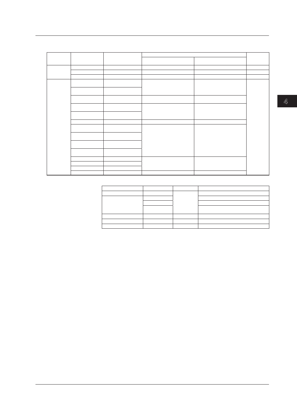
The inputs indicated below can be used on MXLOGGER or the MX100/DARWIN API
(software sold separately).
Input
Measurement
Range Type
Rated Measurement
Range
Measurement Accuracy
Highest
Resolution
(1 Digit)
Integration Time: 16.67 ms
or More
Integration Time: 1.67 ms
DC voltage
60 mV (high res.)
0.000 to 60.000 mV
±(0.05% of rdg + 20 digits)
±(0.1% of rdg + 100 digits)
1 µV
1 V
–1.0000 to 1.0000 V
±(0.05% of rdg + 2 digits)
±(0.1% of rdg + 10 digits)
100 µV
6 V (high res.)
0.0000 to 6.0000 V
±(0.05% of rdg + 20 digits)
±(0.1% of rdg + 100 digits)
100 µV
4-wire RTD
(Measurement
current: 1 mA)
Cu10 at 20°C
alpha = 0.00392
–200.0 to 300.0°C
±(0.1% of rdg + 2°C)
±(0.2% of rdg + 5°C)
0.1°C
Cu10 at 20°C
alpha = 0.00393
–200.0 to 300.0°C
Cu25 at 0°C
alpha = 0.00425
–200.0 to 300.0°C
±(0.1% of rdg + 0.5°C)
±(0.2% of rdg + 2°C)
Cu53 at 0°C
alpha = 0.00426035 –50.0 to 150.0°C
±(0.05% of rdg + 0.3°C)
±(0.1% of rdg + 1.5°C)
Cu100 at 0°C
alpha = 0.00425
–50.0 to 150.0°C
Pt25 (JPt100 × 1/4) –200.0 to 550.0°C
±(0.1% of rdg + 0.5°C)
±(0.2% of rdg + 2°C)
Cu10 GE
(high resolution)
–200.0 to 300.0°C
±(0.1% of rdg + 2°C)
±(0.2% of rdg + 5°C)
Cu10 L&N
(high resolution)
–200.0 to 300.0°C
Cu10 WEED
(high resolution)
–200.0 to 300.0°C
Cu10 BAILEY
(high resolution)
–200.0 to 300.0°C
Pt100 GOST
–200.0 to 600.0°C
±(0.05% of rdg + 0.3°C)
±(0.1% of rdg + 1.5°C)
Cu100 GOST
–200.0 to 200.0°C
Cu50 GOST
–200.0 to 200.0°C
Cu10 GOST
–200.0 to 200.0°C
±(0.1% of rdg + 2°C)
±(0.2% of rdg + 5°C)
Measurement interval, integration time, and filter:
Measurement Interval Integration Time
Filter
Rejected Noise and Notes
100, 200 ms
1.67 ms
Rectangular
600 Hz and its integer multiples*
500 ms
16.67 ms
60 Hz and its integer multiples
20 ms
50 Hz and its integer multiples
Auto
Automatically detects the power supply
frequency and set 16.67 or 20 ms
1 s
36.67 ms
Trapezoidal
50 Hz or 60 Hz and their integer multiples
2 s
100 ms
Rectangular
10 Hz and its integer multiples
5,10, 20, 30, 60 s
200 ms
Cos
Fc = 5-Hz low-pass filter
*
Since the power supply frequency noise is not rejected, the measured vales may fluctuate especially
with temperature measurement and 20 Ω measurement. In such cases, set the measurement interval
to 500 ms or higher.
Maximum input voltage:
DC voltage at 1-V range or less, RTD, resistance, and DI (contact):
±10 VDC (continuous)
Other measurement ranges: ±120 VDC (continuous)
Normal-mode voltage:
DC voltage, DI (LEVEL): 1.2 times the range rating or less (50/60
Hz, peak value including the signal component). The RTD and
resistance ranges indicate the voltage conversion value when
measurement current applied.)
Resistance 2 kΩ, RTD 100 Ω, 500 Ω, 1000 Ω systems: 50 mV peak
Resistance 200 Ω, RTD 10 Ω, 25 Ω, 50 Ω systems: 10 mV peak
Resistance 20 Ω: 4 mV peak
Normal-mode rejection ratio:
RTD and registance ranges are voltage conversion values when
the measured current is flowing.
For integration time of 16.67 ms or more: 40 dB or more (50/60
Hz ±0.1%)
For integration time of 1.67 ms: 50/60 Hz is not rejected
4.7 6-CH, Medium-Speed Four-Wire RTD Resistance Input Module (MX110-V4R-M06) Specifications