Yokogawa PC-Based MX100 User Manual
Page 55
2-10
IM MX100-01E
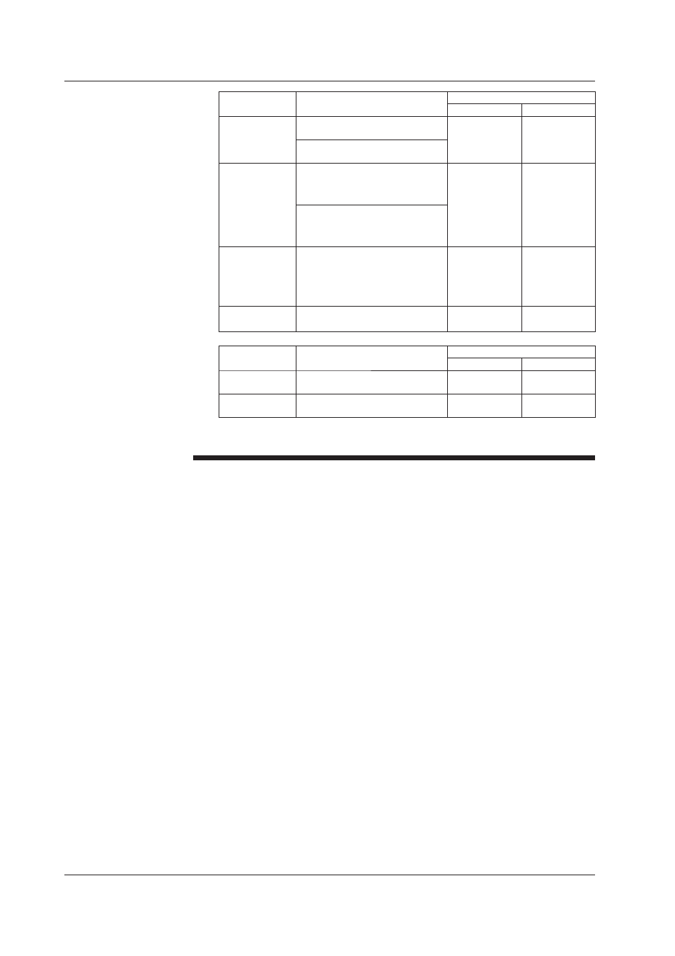
Module Type
Max. Input Voltage
Max. Common Mode Voltage
Between Channels Input to Ground
DCV/TC/DI input
module
± 10 VDC: Voltage range of 1 VDC
or less, TC, and DI (contact)
120 VACrms
(50/60 Hz)
600 VACrms
(50/60 Hz)
± 120 VDC: Voltage range of 2
VDC or more, and DI (LEVEL)
Four-wire RTD
resistance input
module
± 10 VDC: Voltage range of 1 VDC
or less, RTD, resistance, and DI
(contact)
Voltage:
120 VACrms
(50/60 Hz)
RTD and
resistance:
50 VACrms
(50/60 Hz)
600 VACrms
(50/60 Hz)
± 120 VDC: Voltage range of 2
VDC or more, and DI (LEVEL)
Strain input
module
± 10 VDC
30 VACrms
(50/60 Hz)
-B12 and -B35:
250 VACrms
(50/60Hz)
-NDI: 30 VACrms
(50/60Hz)
Digital input
module
-D05: ± 10 VDC
-D24: ± 50 VDC
-
250 VACrms
(50/60 Hz)
Module Type
Max. Input Voltage
Max. Common Mode Voltage
Between Channels Output to Ground
Analog/PWM
output module
-
-
250 VACrms
(50/60 Hz)
Digital output
module
250 VAC or 250 VDC
-
250 VACrms
(50/60 Hz)
• The MX100 is a measurement category II (IEC61010-1) and installation
category II (CSA1N.61010-1) instrument.
Consider the points indicated below to prevent noise from entering the measurement
circuit. For a description of the measures against noise on the MX100, see section 2.7.
• Keep the measurement circuit away from the power supply cable (power supply
circuit) and ground circuit.
• It is desirable that the object under measurement is not a noise source. However, if
this is not avoidable, insulate the object under measurement and the measurement
circuit. In addition, ground the object under measurement.
• Shielded wires are effective against noise caused by electrostatic induction. As
necessary, connect the shield to the ground terminal of the MX100 (make sure this
does not lead to grounding at two points).
• Twisting the measurement circuit wires at short intervals is relatively effective against
noise caused by electromagnetic induction.
• Make sure to ground the protective ground terminal through a small grounding
resistance (less than or equal to 100 Ω).
When using the reference junction compensation of the MX100 through thermocouple
input, take measures to stabilize the temperature at the terminal section.
• Always close and secure the terminal cover.
• Do not use thick wires with high heat radiation effects (cross-sectional area of 0.5
mm
2
or smaller recommended).
• Keep the ambient temperature consistent. Large temperature fluctuations occur in
such cases as when a fan nearby is turned ON/OFF.
Connecting the input wires in parallel with other instruments may mutually affect
the measured values.
If you need to make a parallel connection:
• Turn OFF burnout.
• Ground each instrument at a single common point.
• Do not turn ON/OFF the instrument while measurement is in progress. It may cause
adverse affects on the other instrument.
Note that RTDs and resistors cannot be connected in parallel.
2.4 Connecting the Signal Wires