2 main module functions, Communications, Measurement – Yokogawa PC-Based MX100 User Manual
Page 16: Main module functions -7, Communications -7 measurement -7, Index, Synchronization of measurements
1-7
IM MX100-01E
Explanation of Functions
3
2
1
4
5
Index
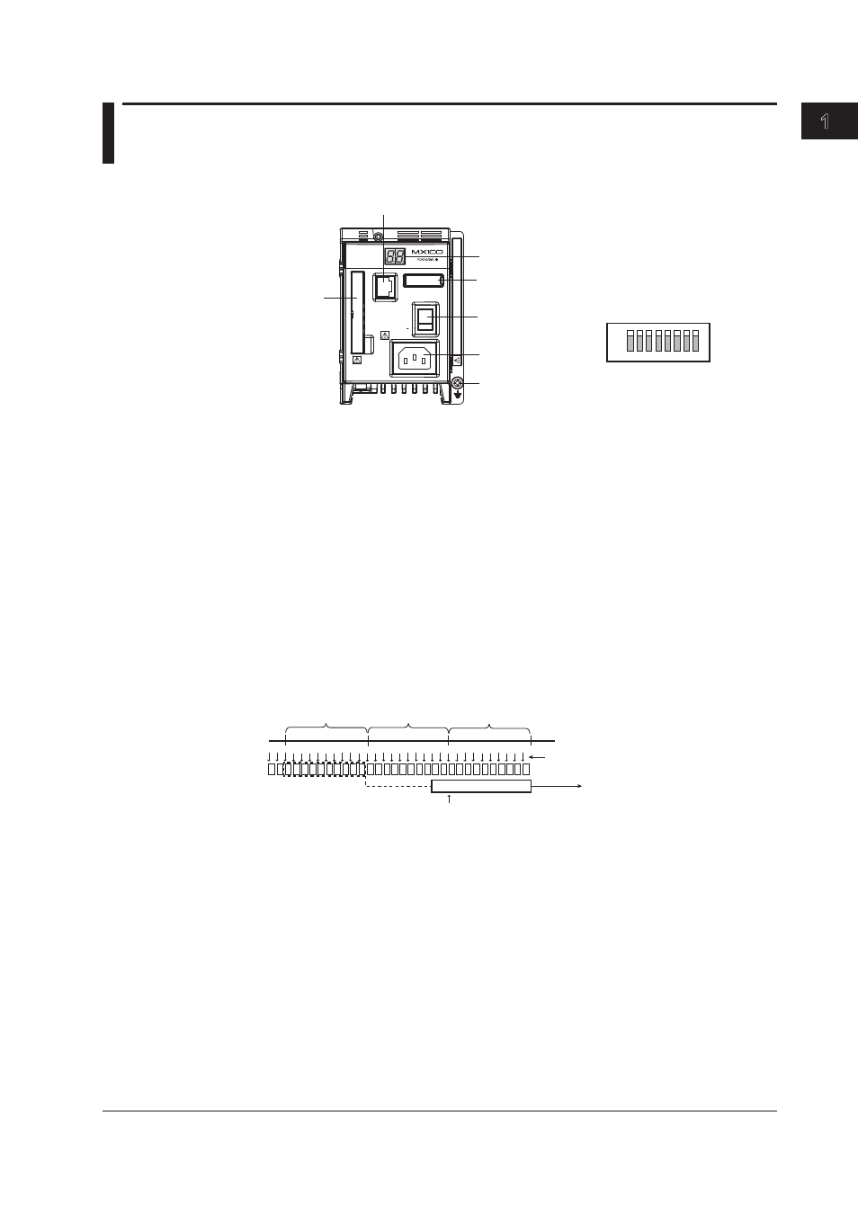
1.2 Main Module Functions
The main module is the heart of the MX100.
Ethernet port
Power switch
CF card
slot
Power connector or
screw terminal
7-segment LED
Dipswitch*
DATA ACQUISITION UNIT
ETHERNET
POWER
10BASE - T
100BASE - TX
100 - 240V AC
Do not operate without reading safety precaution in users manual.
70VA MAX
50/60Hz
SW
ON
1 2 3 4 5 6 7 8
Functional ground terminal
* Normally, turn all switches ON.
If the /DS option function is
enabled (see section 5.1),
you can initialize settings
(see section 2.6) and perform
other functions.
1 2 3 4 5 6 7 8
ON
Communications
The main module is equipped with one auto-negotiating 10BASE-T/100BASE-
TX Ethernet port. The LEDs at the upper-left and lower-left of the port indicate the
communication status of the Ethernet interface.
Measurement
The main module acquires measured data sampled at specified intervals on each input
module is acquired. Correcting computation, conversion to physical quantities, and other
processes are performed on the acquired measured data, followed by transmission
of measured data to a PC via the Ethernet interface at 100-ms intervals (shortest).
Even if sampled at intervals less than 100 ms (10 ms or 50 ms), the data is transmitted
collectively at 100-ms intervals. In addition, the main module receives output commands
sent from the PC as necessary and generates signal output instructions to the output
modules.
100 ms
100 ms
100 ms
Creation of output data
Output by an output request from the PC
Data sampling when the
measurement interval is 10 ms
Timing when the creation of the
output data starts
Synchronization of Measurements
• Synchronization between modules
If set to the same measurement interval, measurements made by input modules in the
same acquisition unit are synchronized.
• Synchronization between channels
On the 4-CH, High-Speed Universal Input modules and 10-CH, high speed digital
input modules (-D05 and -D24), measurements between channels are synchronized.
On the 10-CH, Medium-Speed Universal Input modules, 30-CH, Medium-Speed
DCV/TC/DI Input Modules, 6-CH Medium-Speed Four-Wire RTD Resistance
Input modules, and 4-CH, Medium-Speed Strain Input modules (-B12, -B35, and
-NDI), measurements are made sequentially one channel at a time. Therefore,
measurements are not synchronized between channels (we can consider them
synchronized within the measurement interval).