8 contact input wiring, 1 cable specifications, 2 wiring procedure – Yokogawa Integral Oxygen Analyzer ZR202 User Manual
Page 84: Contact input wiring -12 5.8.1, Cable specifications -12, Wiring procedure -12
<5. Wiring>
5-12
IM 11M12A01-02E
8th Edition : Jan.13,2012-00
5.8
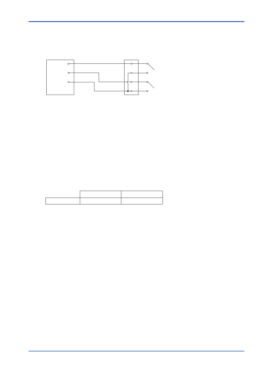
Contact Input Wiring
The converter can execute specified function when receiving contact signals.
To use these contact signals, wire as follows:
ZR402G
Converter
Terminal box
DI-1
DI-C
DI-2
Contact input 1
Contact input 2
F5-14E.ai
Figure 5.13 Contact Input Wiring
5.8.1
Cable Specifications
Use 2-core or 3-core cable for this wiring. Depending on the number of input(s), determine which
cable to use.
5.8.2
Wiring Procedure
(1) M4 screws are used for the terminals of the converter. Each cable should be terminated
corresponding to crimp-on terminals.
(2) The ON/OFF level of this contact input is identified by the resistance. Connect a contact
input that satisfies the specifications in Table 5.2.
Table 5.2 Identification of Contact Input ON/OFF
Closed
Open
Resistance
200 Ω or less
100 kΩ or more