2 piping for system 2, Piping for system 2 -5, Caution – Yokogawa Integral Oxygen Analyzer ZR202 User Manual
Page 65
<4. Pipomg>
4-5
IM 11M12A01-02E
8th Edition : Jan.13,2012-00
4.2
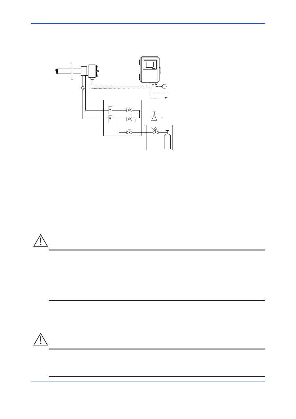
Piping for System 2
Piping in System 2 is illustrated in Figure 4.7.
~
ZA8F Flow Setting Unit
EXA ZR402G
ZR22G Separate type
Zirconia Oxygen Analyzer, Detector
ZR402G Converter
Reference
gas
Calibration
gas
Needle
valve
Flowmeter
Instrument air
Air Set
Pressure
reducing
valve
Zero gas cylinder
Calibration gas
unit case
F4-7E.ai
Stop valve
or Check valve
Span gas
(Same as Zero gas Calibration)
Signal
(6-core shield cable)
Contact input
Analog output, Contact input
Digital output (HART)
Heater (2-core)
100 to
240 V AC
Figure 4.7 Piping for System 2
System 2 illustrated in Figure 4.7 requires piping as follows:
• Connect a stop valve or check valve the nipple at the calibration gas inlet of the detector.
• If a high temperature detector is used and the sample gas pressure is negative, connect an
ejector assembly to the sample gas exhaust hole of the high temperature probe adapter (see
Section 4.1.4, Figure 4.3).
• If a high temperature detector is used and the pressure of the sample gas is 0.49 kPa or higher,
it is recommended that a needle valve (throttle) be used in the sample gas exhaust of the high
temperature probe adapter (see Section 4.1.4, Figure 4.4).
CAUTION
• This is for lowering the sample gas temperature below 700
°C. If the gas temperature is high
and the pressure is also significantly high, the sampled gas temperature may not reduced
below 700
°C when reaching the detector.
On the other hand, if the sample gas temperature is lowered too much, condensation may be
produced in the high temperature probe adapter. During wintertime, it is recommended that
the high temperature probe adapter be protected with an insulating material to prevent
condensation (see Section 4.1.4, Figure 4.5).
For the usage of the high temperature probe adapter, refer to Section 3.2.2.
• If the dust sticking to the interior of the high temperature probe adapter is to be eliminated by
blow back while using the high temperature detector, the air feed for blow back should also be
taken into consideration.
CAUTION
• The probe is easily clogged if too much dust is contained in the sample gas such as in a utility
boiler or cement kiln. To get rid of the dust with compressed air, the piping from the air source
is connected only during cleaning. Blow back piping can be installed for dust cleaning as
illustrated in Section 4.3.1.