Warning, Manual calibration – Yokogawa Integral Oxygen Analyzer ZR202 User Manual
Page 157
<10. Other Functions>
10-19
IM 11M12A01-02E
(1) Use the needle of the zero gas valve “ CHECK GAS “ to puncture a hole in the gas cylinder
installed as described in Section 10.5.2. Fully clockwise turn the valve regulator by hand.
(2) Next, adjust the flow rate to 600 ± 60 ml/min (the flow check ball stops floating on the green
line when the valve is slowly opened). Turn the regulator of the zero gas valves back slowly
counterclockwise. At that time, the flow rate also decreases as the inner pressure of the gas
cylinder decreases. Therefore, monitor the flow check and, when the ball’s position changes
greatly, readjust the valve.
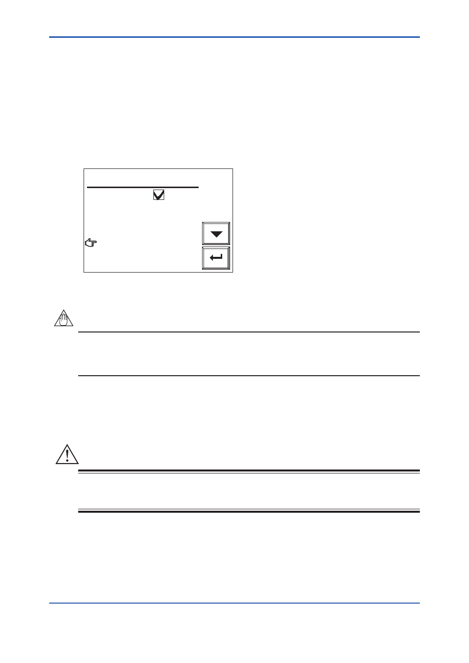
(3) Select “Valve opened” (to start calibration) from the Manual calibration display. Check the
Trend graph display to see that the measured value is stabilized. Then press the [Enter] key.
The Manual calibration display shown in Figure 10.18 appears. Then stop the zero gas flow
immediately. Turn the zero gas valve regulator fully clockwise. If this valve regulator is not
properly adjusted, the needle valve will not close completely and a cylinder gas may leak.
Enter
Zero calibration
Close the zero gas valve.
Span calibration
End
Manual calibration
F10.18E.ai
Figure 10.18 Zero gas Calibration Complete (in Manual Calibration Display)
NOTE
Be sure not to terminate a calibration in progress because of a shortage of gas in the cylinder.
Each gas cylinder is operable for nine minutes or more provided the gas is discharged at the
specified rate. Therefore, if your calibration time is estimated at four minutes, you can operate
the zero-point calibration twice.
(2) Remove the tube connecting the detector to the standard gas unit.
WARNING
Store the standard gas unit with the gas cylinder mounted where the ambient temperature does
not exceed 40 °C. Otherwise, the gas cylinder may explode. Store the spare gas cylinders under
the same condition.
8th Edition : Jan.13,2012-00