Yokogawa Integral Oxygen Analyzer ZR202 User Manual
Page 177
<12. Troubleshooting>
12-7
IM 11M12A01-02E
(4) Check whether the deterioration of or damage to the sensor assembly that caused the
alarm has occurred suddenly during the current calibration in the following procedure:
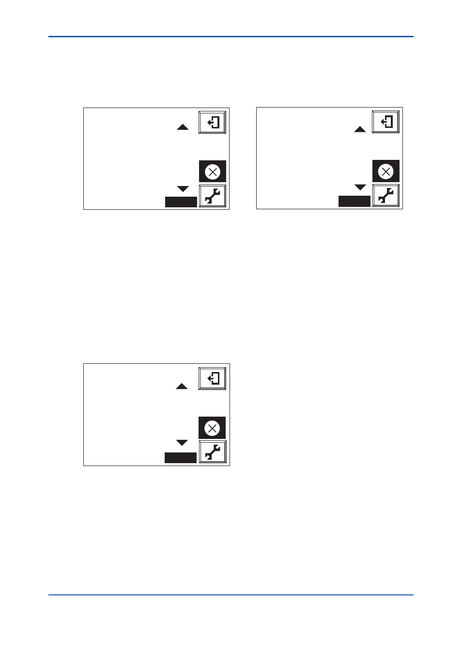
a. Call up the Detailed-data Display.
b. Use the [Page Scroll] key to check Calibration Data (Figure 12.6). The span and zero
correction ratios of the last ten calibration can be checked here. By checking these data,
whether the sensor deterioration has occurred suddenly or gradually can be determined.
Cell voltage:
0 . 6 mV
Thermo voltage:
4 2 . 1 mV
C.J.resistance: 1 1 8 1 . 4 Ω
Cell resistance:
- 4 Ω
Soft.rev.:
0 . 2 4
Tag:
F12.5E.ai
Hold
Calibration data:
1: 2 0 0 0 / 07 / 07 1 4 : 57
Span gas ratio: - 2 . 9 %
Zero gas ratio: 7 0 . 3 %
2: 2 0 0 0 / 07 / 07 1 4 : 5 4
Span gas ratio: - 2 . 9 %
Zero gas ratio: 8 9 . 7 %
Tag:
Hold
Figure 12.5 Detailed Data Display
Figure 12.6 Calibration History
(5) If the sensor assembly has deteriorated suddenly, the check valve that prevents moisture in
the furnace from entering into the calibration pipes may have malfunctioned. If the furnace
gas flows into calibration lines, the gas is cooled and thus condensation develops and
accumulates in the pipe. During calibration the condensate is carried with the calibration gas
and blow onto the sensor assembly, whereby the cell is cooled quickly. This results in the
failed sensor assembly.
(6) If the sensor assembly has deteriorated gradually, check the condition of the sensor
assembly following the procedure below.
a. Use the [Page Scroll] key to check Cell Resistance. It should be 200V or less if the cell
(sensor) is new. On the other hand, if the cell (sensor) is approaching the end of its service
life, it will be 3 to 10 kV.
b. Use the [Page Scroll] key to check Cell Robustness. It should say “Life > 1 year” if the cell
(sensor) is in good condition.
Span gas ratio: - 2 . 9 %
Zero gas ratio: 7 0 . 3 %
Response time: 0 s
Cell robustness: life< 1 month
Cell temperature: 1 0 6 7 °C
C.J.temperature: 4 7 °C
Tag:
Hold
F12.7E.ai
Figure 12.7
12.2.2.3 Alarm 7: Span-point Calibration Coefficient Alarm
In automatic or semi-automatic calibration, this alarm is generated when the span correction ratio
is out of the range of 0 ± 18% (refer to Section 9.1.3, Compensation).
The following are suspected as the cause:
(1) The oxygen concentration of the span gas does not agree with the value of the span gas set
in Calibration setup.
(2) The flow of the span gas is out of the specified flow value (600 ± 60 ml/min).
(3) The sensor assembly is damaged and the cell voltage is abnormal.
8th Edition : Jan.13,2012-00