1 piping parts for system 2, 2 piping for the calibration gas, Piping parts for system 2 -6 – Yokogawa Integral Oxygen Analyzer ZR202 User Manual
Page 66: Piping for the calibration gas -6
<4. Pipomg>
4-6
IM 11M12A01-02E
8th Edition : Jan.13,2012-00
4.2.1
Piping Parts for System 2
Check that the parts listed in Table 4.2 are ready.
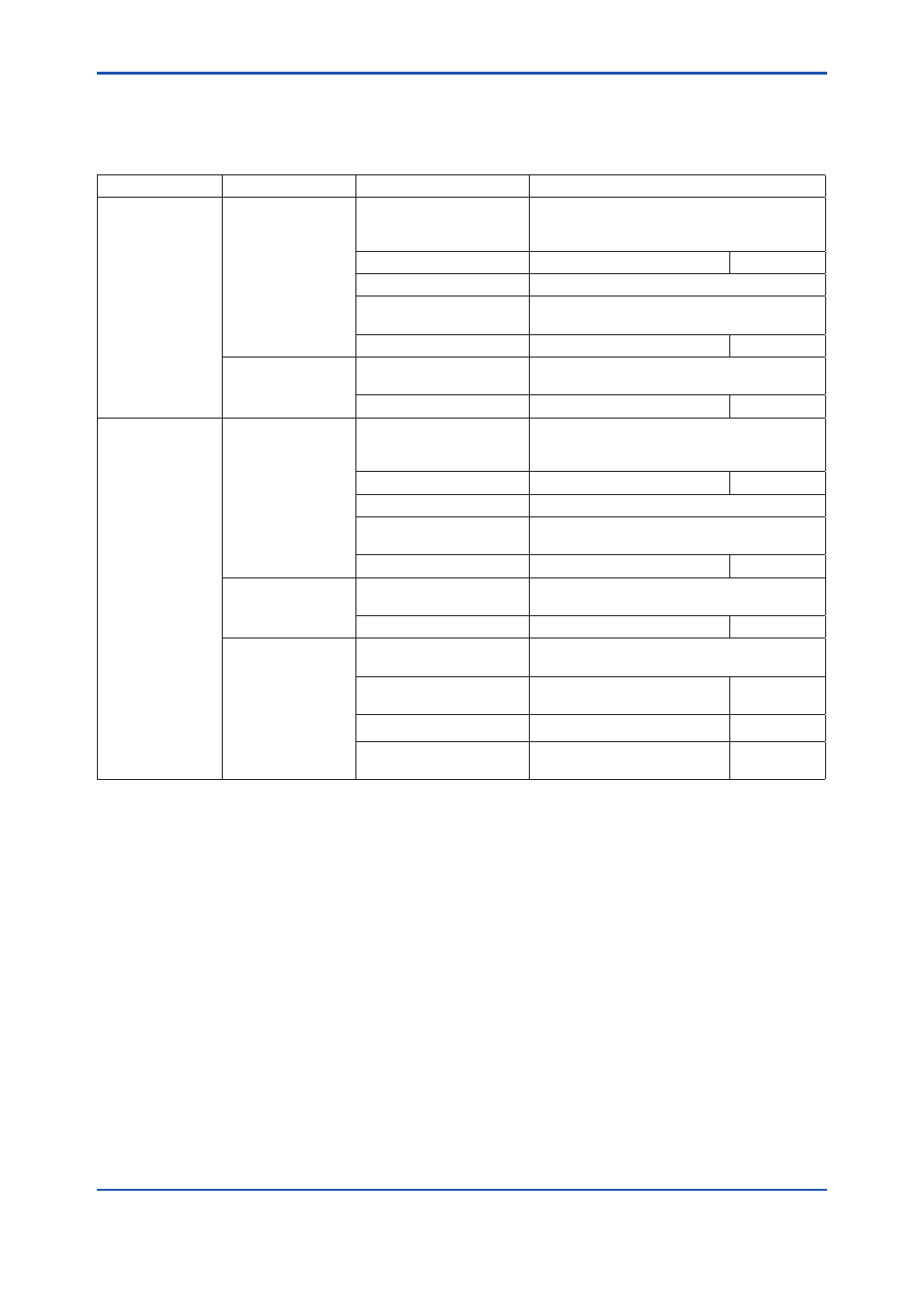
Table 4.2 Piping Parts
Detector
Piping location
Parts Name
Note
General use
detector
Calibration gas inlet Stop valve or check valve Recommended by YOKOGAWA (L9852CB or
G7016XH) Provided by YOKOGAWA
(K9292DN or K9292DS)
Nipple *
Rc1/4 or 1/4 NPT
General parts
Zero gas cylinder
User´s scope
Pressure reducing valve
Recommended by YOKOGAWA (G7013XF or
G7014XF)
Joint for tube connection
Rc1/4 or 1/4 NPT
General parts
Reference gas inlet Air set
Recommended by YOKOGAWA (G7003XF/
K9473XK or G7004XF/K9473XG)
Joint for tube connection
Rc1/4 or 1/4 NPT
General parts
High temperature
Detector
(0.15 m)
Calibration gas inlet Stop valve or check valve Recommended by YOKOGAWA (L9852CB or
G7016XH) Provided by YOKOGAWA
(K9292DN or K9292DS)
Nipple *
Rc1/4 or 1/4 NPT
General parts
Zero gas cylinder
User´s scope
Pressure reducing valve
Recommended by YOKOGAWA (G7013XF or
G7014XF)
Joint for tube connection
Rc1/8 or 1/8 NPT
Reference gas inlet Air set
Recommended by YOKOGAWA (G7003XF/
K9473XK or G7004XF/K9473XG)
Joint for tube connection
Rc1/4 or 1/4 NPT
General parts
Sample gas outlet
Ejector assembly *
Recommended by YOKOGAWA (E7046EC or
E7046EN)
T-shaped joint of the same
diameter *
R1/4 or 1/4 NPT
General parts
Needle valve *
Rc1/4 or 1/4 NPT
General parts
Nipple of other diameter * R1/2 to R1/4 or R1/2 to 1/4
NPT
General parts
Note: Parts with marking * are used when required.
General parts can be found on the local market.
4.2.2
Piping for the Calibration Gas
This piping is to be installed between the zero gas cylinder and the ZA8F flow setting unit, and
between the ZA8F flow setting unit and the ZR22G detector.
The cylinder should be placed in a case assemble E7044KF or the like to avoid any direct
sunlight or radiant heat so that the gas cylinder temperature does not exceed 40
°C.
Mount a reducing valve (specified by YOKOGAWA) on the cylinder.
Mount a check valve or stop valve (specified by YOKOGAWA) on the nipple (found on the local
market) at the calibration gas inlet of the detector as illustrated in Figure 4.8.
(The check valve or the stop valve may have been mounted on the detector when shipped.)
Connect the flow setting unit and the detector to a stainless steel pipe 6 mm (O.D.) x 4 mm or
larger (I.D.) (or nominal size 1/4 inch).