4 wiring for analog output, 1 cable specifications, 2 wiring procedure – Yokogawa Integral Oxygen Analyzer ZR202 User Manual
Page 81: 5 power and grounding wiring, 1 power wiring, Wiring for analog output -9 5.4.1, Cable specifications -9, Wiring procedure -9, Power and grounding wiring -9 5.5.1, Power wiring -9
<5. Wiring>
5-9
IM 11M12A01-02E
8th Edition : Jan.13,2012-00
5.4
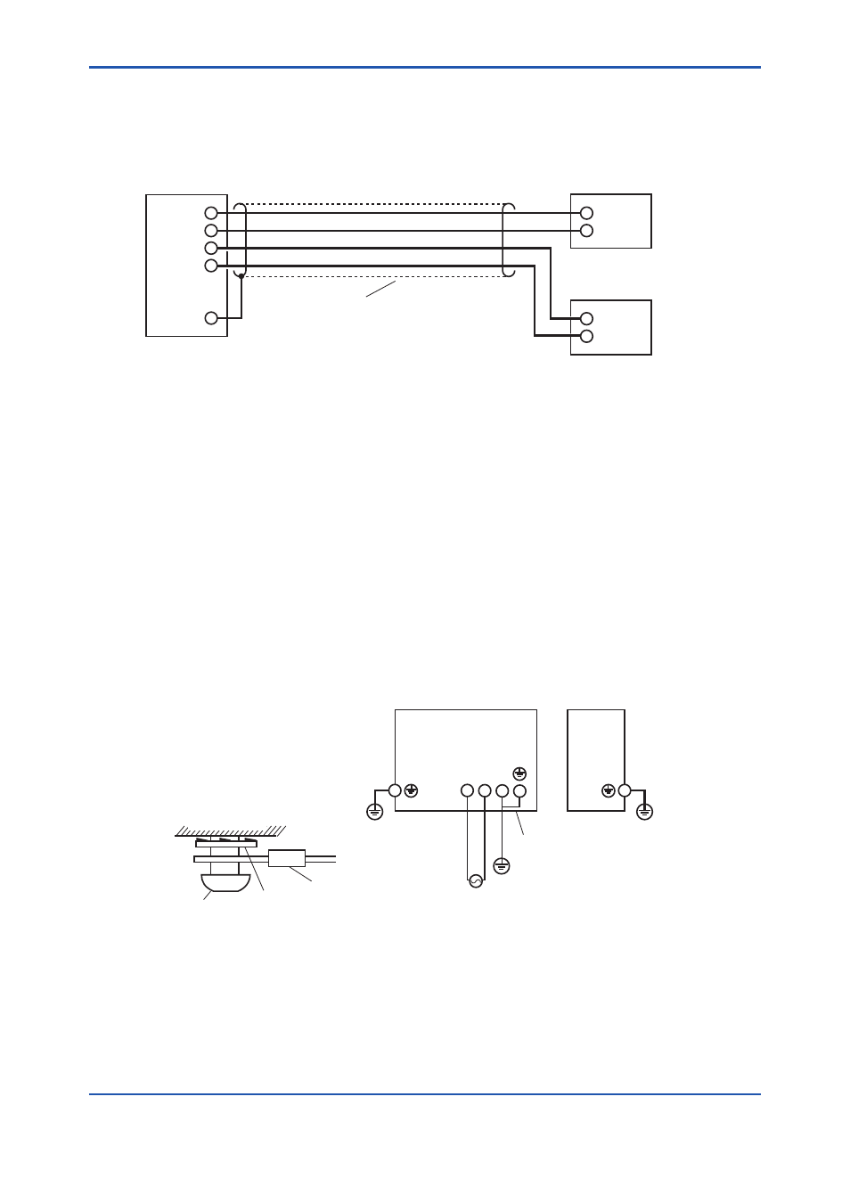
Wiring for Analog Output
This wiring is for transmitting 4 to 20 mA DC output signals to a device, e.g. recorder.
Maintain the load resistance including the wiring resistance at 550 Ω or less.
Shielded cable
Receiver 1
Receiver 2
ZR402G
Converter
1
2
1
2
AO-1(+)
AO-1(-)
AO-2(+)
AO-2(-)
FG
F5-9E.ai
Figure 5.8 Wiring for analog output
5.4.1
Cable Specifications
For this wiring, use a 2-core or a 4-core shielded cable.
5.4.2
Wiring Procedure
(1) M4 screws are used for the terminals of the converter. Each wire in the cable should be
terminated corresponding to crimp-on terminals. Ensure that the cable shield is connected
to the FG terminal of the converter.
(2) Be sure to connect “+” and “-” polarities correctly.
5.5
Power and Grounding Wiring
This wiring supplies power to the converter and grounds the converter/detector.
ZR402G
Converter
Jumper plate
L N G
ZR22G
Detector
Ground
100 - 240 V AC
50/60 Hz
Grounding to the ground terminal
on the converter case
Converter case
FG terminal Lock washer
Crimp-on terminal of
the ground wire
F5-10E.ai
Figure 5.9 Power and Grounding wiring
5.5.1
Power Wiring
Connect the power wiring to the L and N terminals of the converter. Proceed as follows:
(1) Use a 2-core or a 3-core cable.
(2) The size of converter terminal screw threads is M4. Each cable should be terminated
corresponding to crimp-on terminals.