3 operating the zero gas flow setting valve, 4 operation after calibration, Manual calibration – Yokogawa Integral Oxygen Analyzer ZR202 User Manual
Page 159
<10. Other Functions>
10-21
IM 11M12A01-02E
10.6.3 Operating the Zero Gas Flow Setting Valve
Operate the zero gas flow setting valve during zero-point calibration in the following procedures:
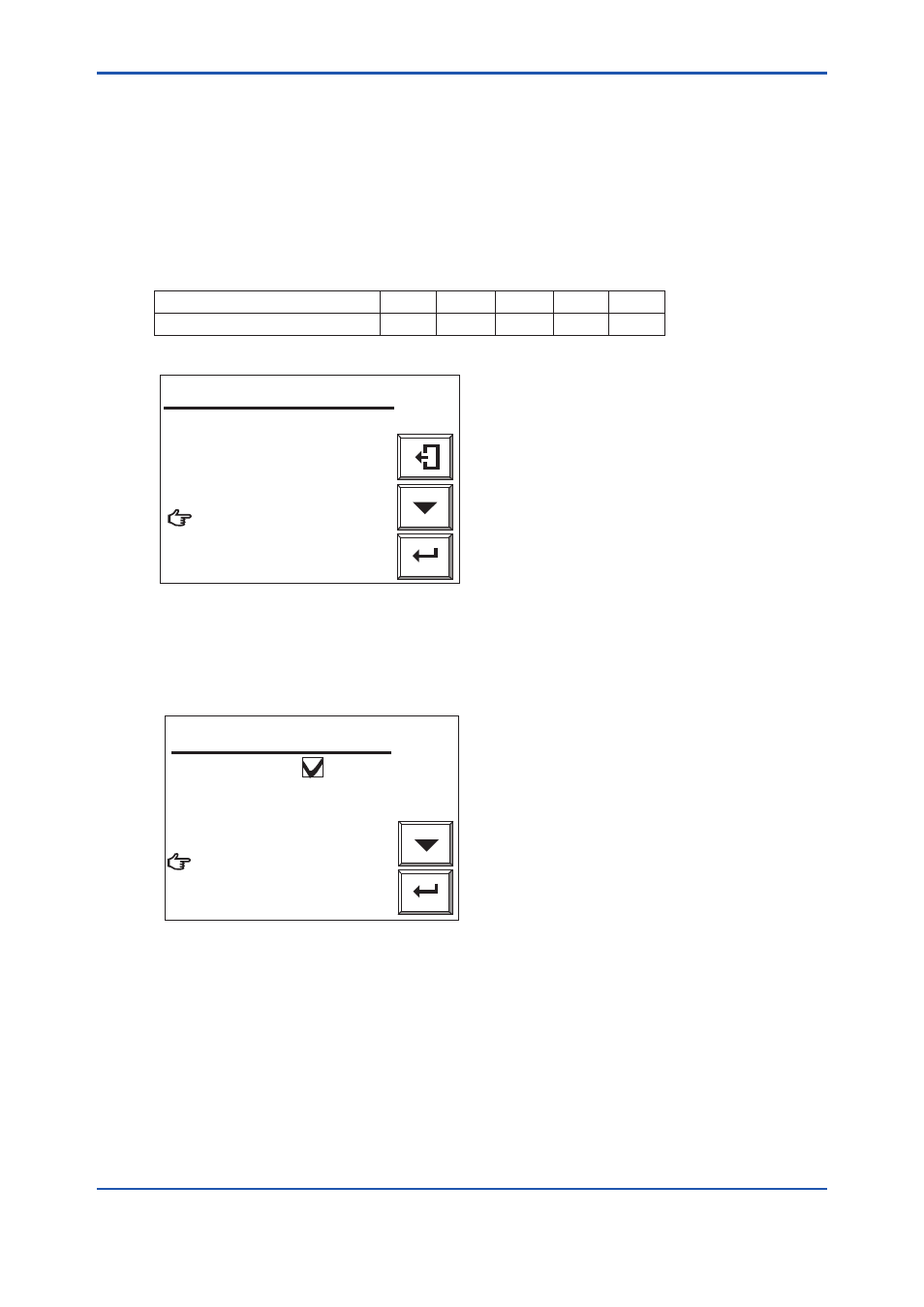
(1) When the display shown in Figure 10.19 appears during calibration, open the zero gas
flow setting valve of the flow setting unit and adjust the flow rate to 600 ± 60 ml/ min. To
rotate the valve shaft, if the valve has a lock nut loosen the lock nut and slowly turn it
counterclockwise. To check the flow rate, monitor the calibration gas flowmeter.
If the sample gas pressure is extremely high, adjust the sample gas pressure to obtain
pressures (listed in Table 10.6) ± 10%.
Table 10.6
Sample gas pressure (kPa)
50
100
150
200
250
Flow rate (ml/min)
500
430
380
350
320
Enter
Open zero gas valve.
Set flow zero gas to
600ml/min.
Valve opened
Cancel calibration
Manual calibration
F10.19E.ai
Figure 10.19 Manual Calibration Display
(2) Adjust the flow rate and select “Valve opened” from the Manual calibration display.
Check the Trend graph display to see that the measured value is stabilized. Then press the
[Enter] key. The Manual calibration display shown in Figure 10.20 appears.
Enter
Zero calibration
Close the zero gas valve.
Span calibration
End
Manual calibration
F10.20E.ai
Figure 10.20 Zero-point Calibration Complete (in Manual Calibration)
(3) Close the zero gas flow setting valve to stop the zero gas flow. If the valve has a lock nut,
be sure to tighten the lock nut to prevent the any leakage of the zero gas into the sensor
because the valve may become loose during measurement.
10.6.4 Operation After Calibration
No special operation of the instrument is needed after calibration. However, it is recommended
that the pressure reducing valve for the zero gas cylinders be closed because calibration is not
required so often.
8th Edition : Jan.13,2012-00