External dimensions, Piping diagram, Specifications – Yokogawa Integral Oxygen Analyzer ZR202 User Manual
Page 37: 2b pipe mounting example
<2. Specifications>
2-19
IM 11M12A01-02E
8th Edition : Jan.13,2012-00
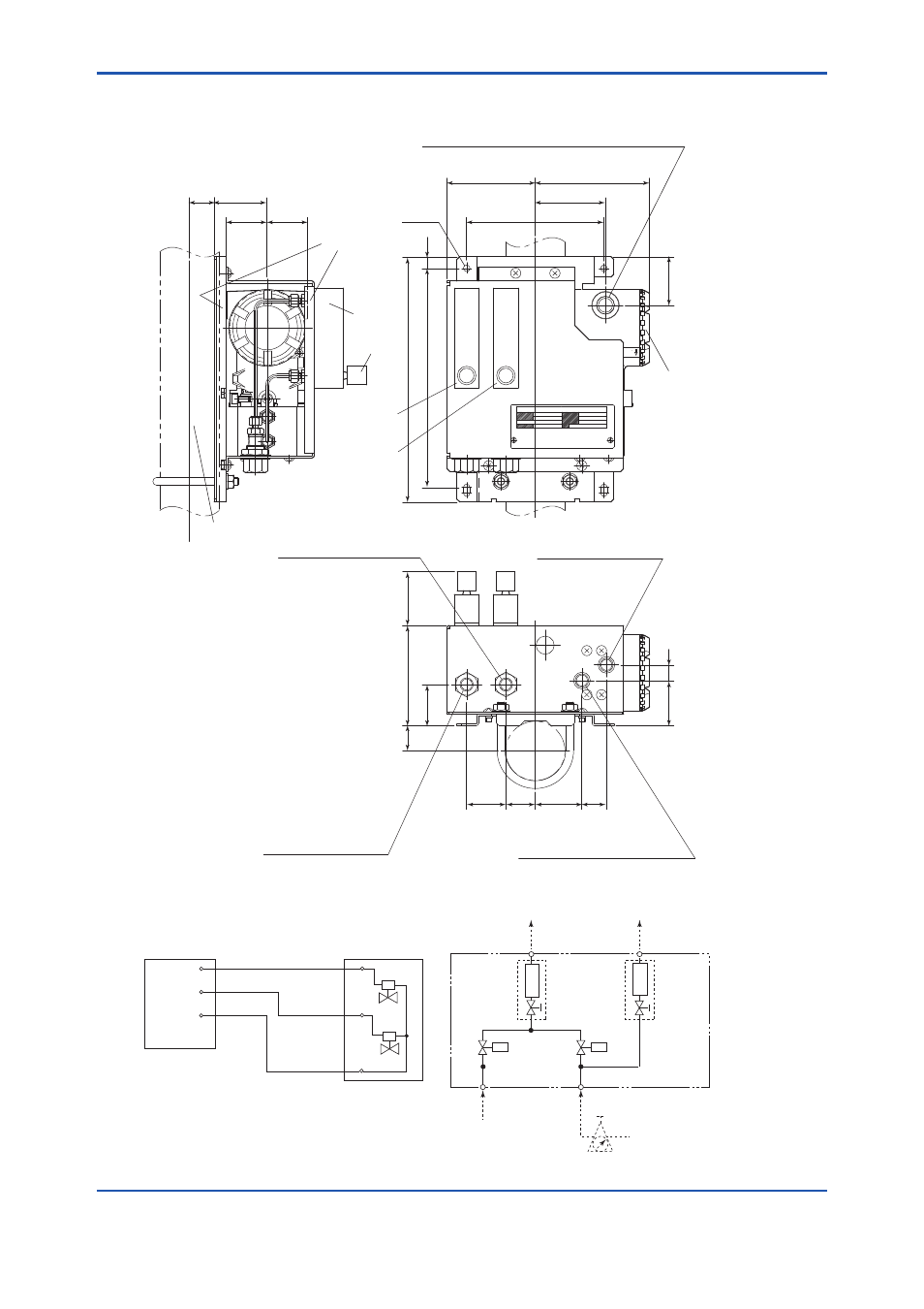
● External Dimensions
F2-6_2E.ai
Unit: mm
OCK
140
250
42
26
41.2
41.2
54
71.5
26
49.5
12
223
46
16
30
40
47.5
25
102
MAX
58
90
116.5
*1 with four ISO M6 screws can wall-mount
*1
4 - Ø6.5
(wiring inlet is at same position on rear)
Flowmeter
Needle valve
2B mounting pipe
Connection port
Setting Valve for
calibration gas
Setting Valve for
reference gas
Wiring inlet ; 2-G1/2,Pg13.5,M20X1.5 or 1/2NPT(Female)
Calibration gas outlet
Rc1/4 or 1/4 NPT(Female)
Zero gas inlet
Rc1/4 or 1/4 NPT(Female)
Reference gas inlet
Rc1/4 or 1/4 NPT(Female)
Rc1/4 or 1/4 NPT(Female)
Reference gas outlet
2B pipe mounting example
Terminal box
• Piping Diagram
ZR402G Converter
ZR40H Automatic
Calibration Unit
AC-Z
AC-C
AC-S
Zero
Span
F35_00.ai
EV1
EV2
CHECK
OUT
ZERO GAS IN
AIR IN
Instrument air Approx. 1.5 l/min
*2
Needle valve is supplied as on accessory with flowmeter
Flowmeter
Flowmeter
REF
OUT
*2
*2
Solenoid valve
EV1,2
EV1
EV2
F2-6_3E.ai