1 blow back piping, Blow back piping -9 – Yokogawa Integral Oxygen Analyzer ZR202 User Manual
Page 69
<4. Pipomg>
4-9
IM 11M12A01-02E
8th Edition : Jan.13,2012-00
4.3.1
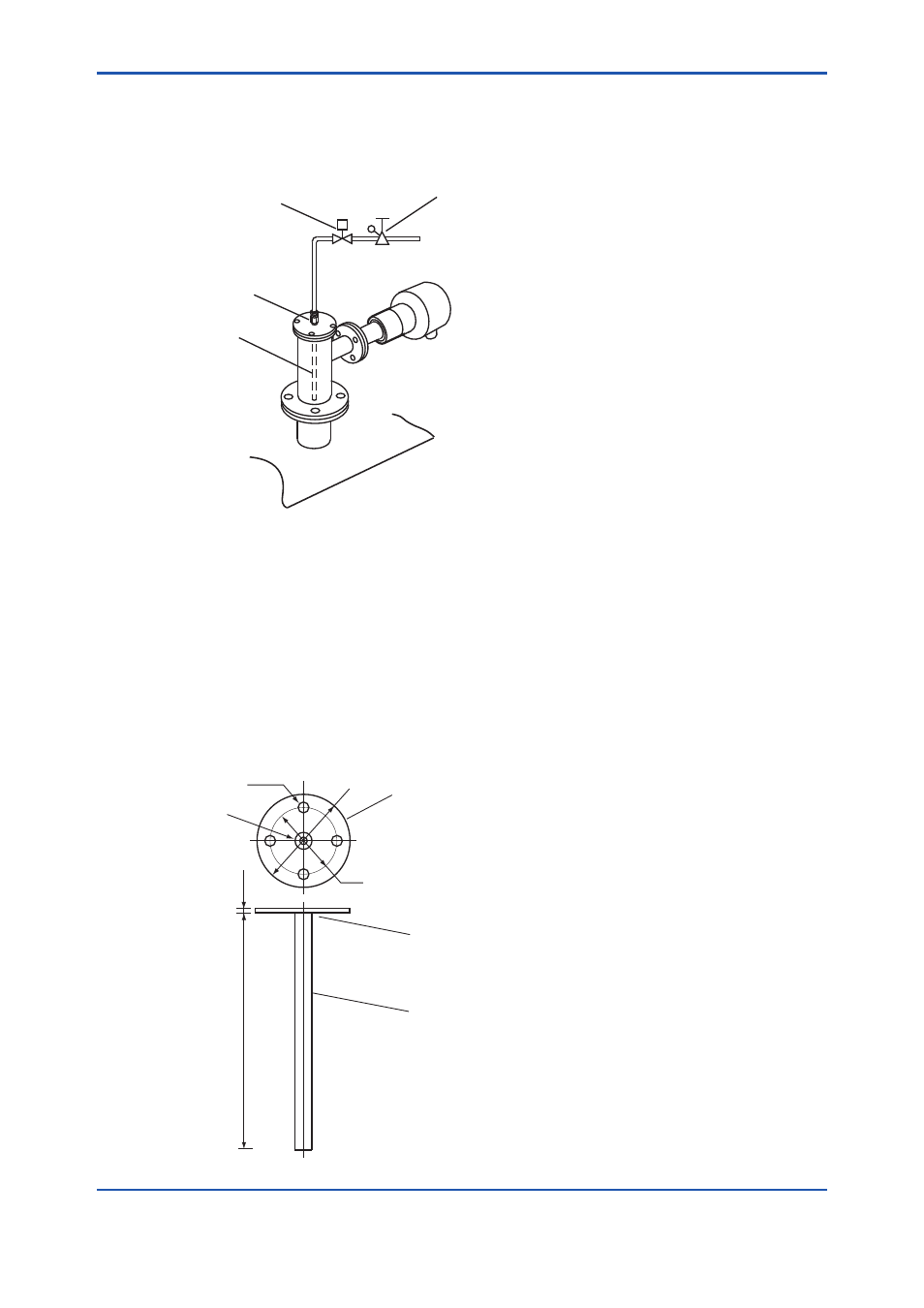
Blow Back Piping
This piping is required when the blow back function is carried out. The piping described below
provides automatic blow back operation when the “ Blow back start “ command is entered to the
converter.
Solenoid valve
Pipe junction
Blow pipe
F4-10E.ai
Pressure reducing valve
Figure 4.11 Blow back Piping
The following parts are required for blow back piping.
• Flange (to be prepared as illustrated in Figure 4.12.)
• Blow pipe (to be prepared as illustrated in Figure 4.12.)
• Two-way solenoid valve: “ Open “ when electric current is on. (Found on the local market) .
• Air set (recommended by YOKOGAWA, G7003XF / K9473XK or G7004XF / K9473XG)
probe adapter.
Approximately
200
Rc1/4
Stainless steel flange
Welded
8 (O.D.) by 6 (I.D.) Stainless steel pipe
F4-11E.ai
Unit : mm
8 ~ 10
Φ
90
Φ
73
4-
Φ
9
Figure 4.12 Manufacturing Blow pipe and Flange