5 input contact settings, 1 input contact functions, Input contact settings -13 8.5.1 – Yokogawa Integral Oxygen Analyzer ZR202 User Manual
Page 119: Input contact functions -13, Caution
<8. Detailed Data Setting>
8-13
IM 11M12A01-02E
8.5
Input Contact Settings
8.5.1
Input Contact Functions
The converter input contacts execute set functions by accepting a remote dry-contact (“voltage-
free contact”) signal. Table 8.7 shows the functions executed by a remote contact signal.
Table 8.7 Input Contact Functions
tem
Function
Calibration gas pressure low
Contact input disables Semi-automatic or Automatic Calibration.
Measuring range change
While Contact signal is ON, range of mA-Output 1 is switched to 0-25
vol%O
2
and “Range” is displayed on the screen. See Figure 8.9.
Calibration start
Contact input starts Semi-Automatic Calibration. Calibration Mode
setting must be [Semi_Auto] or [Auto]. Contact signal must be
applied for at least 1 sec. Even if input signal continues to be applied,
calibration is not repeated unless contact input is released then
reapplied.
Process upset
(Combustible gas detection)
If the Contact signal is ON, heater power will be switched off. (A
one- to 11-second time interval single-output signal is available as
a contact signal.) If this operation starts, the sensor temperature
decreases and an error occurs. To restore it to normal, turn the power
off and then back on, or reset the analyzer.
Blow back start
Contact input starts Blow back. Contact signal must be applied for at
least 1 sec. Even if input signal continues to be applied, Blow back is
not repeated unless contact input is released then reapplied. (Refer
to Section 10.2, Blow Back.)
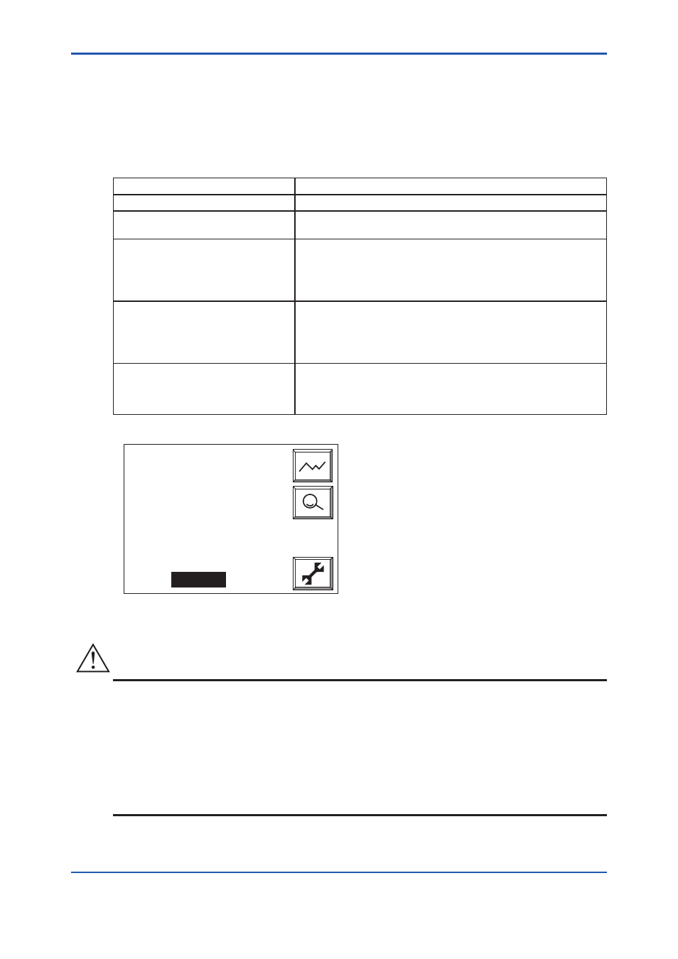
Tag:
21.0
%O
2
7.35mA -Output1
7.35mA -Output2
Range
F8.9E.ai
Figure 8.9 Changing Measuring Range with Input Contact
CAUTION
1. Measurement range switching function by an external contact input is available for analog
output1 only.
2. When making a semi-automatic calibration, be sure to set the semi-automatic or automatic
mode using the Calibration setup display.
3. When carrying out “Blow back,” be sure to set “Blow back” in the output contact setup.
4. When the combustible gas detection signal is sent to the contact input, the converter will cut
the power supply to the heater of the detector. As a result, the heater temperature becomes
low and Error 1 or Error 2 happens.
8th Edition : Jan.13,2012-00