Manual calibration – Yokogawa Integral Oxygen Analyzer ZR202 User Manual
Page 156
<10. Other Functions>
10-18
IM 11M12A01-02E
The standard gas unit is used only when manual calibration is employed. Therefore, the timing
for flowing span gas (air) is included in the manual calibration flowchart described in Section
10.5.2. For operation of the converter, see Section 7.12, earlier in this manual.
(1) When the message “Open span gas valve” is displayed on the converter display during
calibration, plug the power cord into the power supply socket to start the pump of the
standard gas unit.
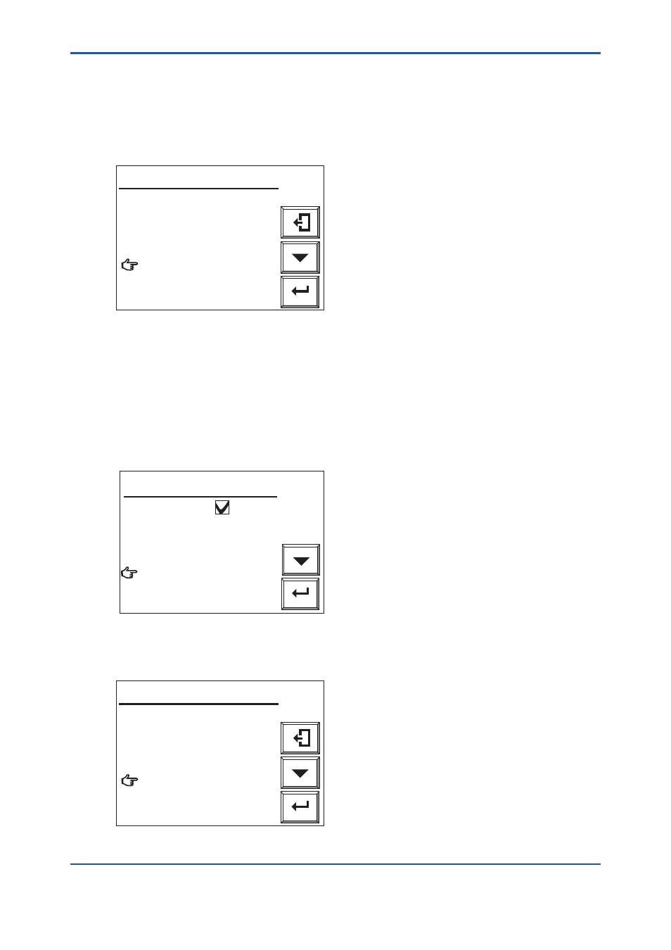
Enter
Open span gas valve.
Set flow span gas to
600ml/min.
Valve opened
Cancel calibration
Manual calibration
F10.15E.ai
Figure 10.15 Manual Calibration Display
(2) Next, adjust the flow rate to 600 ± 60 ml/min using the span gas valve “AIR” (the flow check
ball stops floating on the green line when the valve is slowly opened). To rotate the valve
shaft, loosen the lock nut and turn it using a flat-blade screwdriver. Turning the valve shaft
counterclockwise increases the flow rate.
(3) After adjusting the flow rate, tighten the valve lock nut.
(4) Select “Valve opened” (to start calibration) from the Manual calibration display shown in
Figure 10.15. Check the Trend graph display to see that the measured value is stabilized.
Then press the [Enter] key. The Manual calibration display shown in Figure 10.16 appears.
Disconnect the power cord to stop the pump.
Enter
Span calibration
Close the span gas valve.
Zero calibration
End
Manual calibration
F10.16E.ai
Figure 10.16 Manual Calibration Display
Cause a zero gas to flow according to the Manual calibration display shown in Figure 10.17.
Enter
Open zero gas valve.
Set flow zero gas to
600ml/min.
Valve opened
Cancel calibration
Manual calibration
F10.17E.ai
Figure 10.17 Manual Calibration Display
8th Edition : Jan.13,2012-00