Caution – Yokogawa Integral Oxygen Analyzer ZR202 User Manual
Page 71
<4. Pipomg>
4-11
IM 11M12A01-02E
8th Edition : Jan.13,2012-00
CAUTION
• As far as possible do not stop the instrument air flow, to prevent the sample gas from
entering the detector and damaging the zirconia cell.
• Connect the stop valve, which is at the calibration gas inlet, directly to the detector.
If there is piping between the detector and the valve, condensation may damage the sensor
by rapid cooling when calibration gas is introduced.
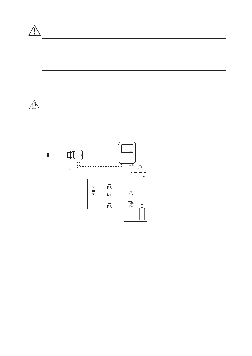
Figure 4.14 illustrates an example of System 2 using a detector with pressure compensation.
Supply air pressure (flow) may vary depending on the furnace pressure. It is recommended to
use a flowmeter and an air set that is suitable for the furnace pressure.
NOTE
• When using the ZA8F Flow Setting Unit and ZR40H Automatic Calibration Unit, please note
that the supplying airflow (pressure) will vary depending on the furnace pressure.
~
ZA8F Flow Setting Unit
EXA ZR402G
ZR22G Separate type
Zirconia Oxygen Analyzer, Detector
ZR402G Converter
Reference
gas
Calibration
gas
Stop valve
or
Check valve
Needle
valve
Flowmeter
Instrument air
Air Set
Pressure
reducing
valve
Zero gas cylinder
Calibration gas
unit case
F4-13E.ai
Span gas
(Same as Zero gas calibration unit)
100 to
240 V AC
Contact input
Analog output, Contact output
Digital output (HART)
Signal
(6-core shield cable)
Heater (2 core cable)
Figure 4.14 System 2 using a detector with pressure compensation