Model and codes – Yokogawa Integral Oxygen Analyzer ZR202 User Manual
Page 22
<2. Specifications>
2-4
IM 11M12A01-02E
8th Edition : Jan.13,2012-00
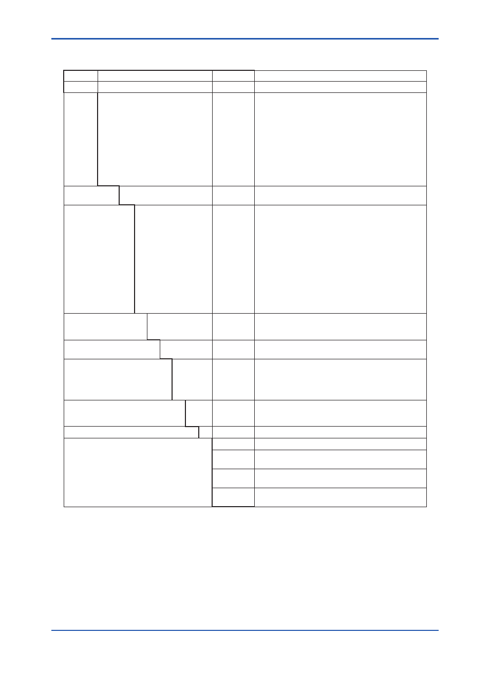
Model and Codes
Style : S2
Model
Suffix code
Option code
Description
ZR22G
- - - - - - - - - - - - - - - - - - - - - - - - - - - - - - - - - - - - - - - - - - - -
Separate type Zirconia Oxygen Analyzer, Detector
Length
-015
-040
-070
-100
-150
-200
-250
-300
-360
-420
-480
-540
- - - - - - - - - -
- - - - - - - - - -
- - - - - - - - - -
- - - - - - - - - -
- - - - - - - - - -
- - - - - - - - - -
- - - - - - - - - -
- - - - - - - - - -
- - - - - - - - - -
- - - - - - - - - -
- - - - - - - - - -
- - - - - - - - - -
0.15 m (for high temperature use) (*1)
0.4 m
0.7 m
1.0 m
1.5 m
2.0 m
2.5 m (*2)
3.0 m (*2)
3.6 m (*2)
4.2 m (*2)
4.8 m (*2)
5.4 m (*2)
Wetted material
-S
-C
- - - - - - - - - -
- - - - - - - - - -
SUS316
Stainless steel with Inconel calibration gas tube (*10)
Flange
(*3)
-A
-B
-C
-E
-F
-G
-K
-L
-M
-P
-Q
-R
-S
-W
- - - - - - - - - -
- - - - - - - - - -
- - - - - - - - - -
- - - - - - - - - -
- - - - - - - - - -
- - - - - - - - - -
- - - - - - - - - -
- - - - - - - - - -
- - - - - - - - - -
- - - - - - - - - -
- - - - - - - - - -
- - - - - - - - - -
- - - - - - - - - -
- - - - - - - - - -
ANSI Class 150 2 RF SUS304
ANSI Class 150 3 RF SUS304
ANSI Class 150 4 RF SUS304
DIN PN10 DN50 A SUS304
DIN PN10 DN80 A SUS304
DIN PN10 DN100 A SUS304
JIS 5K 65 FF SUS304
JIS 10K 65 FF SUS304
JIS 10K 80 FF SUS304
JIS 10K 100 FF SUS304
JIS 5K 32 FF SUS304 (for high temperature use) (*4)
JPI Class 150 4 RF SUS304
JPI Class 150 3 RF SUS304
Westinghouse
Reference gas
-C
-E
-P
- - - - - - - - - -
- - - - - - - - - -
- - - - - - - - - -
Natural convection
External connection (Instrument air) (*11)
Pressure compensated (*11)
Gas Thread
-R
-T
- - - - - - - - - -
- - - - - - - - - -
Rc 1/4
1/4 NPT(Female)
Connection box thread
-P
-G
-M
-T
-Q
- - - - - - - - - -
- - - - - - - - - -
- - - - - - - - - -
- - - - - - - - - -
- - - - - - - - - -
G1/2
Pg13.5
M20 x1.5 mm
1/2NPT
Quick connect (*9)
Instruction manual
-J
-E
-C
- - - - - - - - - -
- - - - - - - - - -
- - - - - - - - - -
Japanese
English
Chinese
—
-A - - - - - - - - - -
Always -A
Options
Valves
Filter
Tag plates
/C
Inconel bolt (*5)
/CV
/SV
Check valve (*6)
Stop valve (*6)
/F1
/F2
Dust Filter (*7)
Dust Guard Protector (*7)
/SCT
/PT
Stainless steel tag plate (*8)
Printed tag plate (*8)
*1
Used with the ZO21P High Temperature Probe Adapter. Select flange (-Q).
*2
When installing horizontally the probe whose insertion length is 2.5 meters or more, use the Probe Protector. Be sure to
specifyZO21R-L-200-
□
. Specify the flange suffix code either -C or -K.
*3
The thickness of the flange depends on its dimensions.
*4
Not used in conjunction with -P (pressure compensation) for reference gas. The flange thickness does not conform to JIS
specification
*5
Inconel probe bolts and U shape pipe are used. Use this option for high temperature use (ranging from 600 to 700 °C).
*6
Specify either /CV or /SV option code.
*7
Not used with the high temperature humidity analyzer.
*8
Specify either /SCT or /PT option code.
*9
Not waterproof, avoid rain. Operating maximum temperature is 80°C. Available only in the U.S.
*10 Recommended if sample gas contains corrosive gas like chlorine.
*11 Piping for reference gas must be installed to supply reference gas constantly at a specified flow rate.