2 vga connector, 3 vga dac filter, 4 routing guide line – IEI Integration ICE-DB-9S User Manual
Page 93: Figure 4-41: vga connector d-sub15
ICE Module
Page 80
line.
5-8,10
GND
Analog and Digital GND
9
DDC_POWER
5V DDC supply voltage for monitor
EEPROM
4,11
NC
Not
Connected
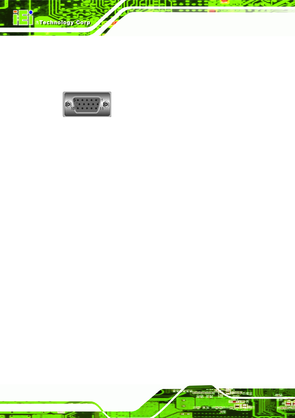
4.13.2 VGA Connector
Figure 4-41: VGA Connector D-SUB15
4.13.3 VGA DAC Filter
A video filter is required for each CRT DAC output. This video filter is to be placed in
close proximity to the VGA connector. The separation between each of the three video
filters for the RGB channels should be maximized if possible to minimize crosstalk.
4.13.4 Routing Guide Line
4.13.4.1 HSYNC and VSYNC Signals
The horizontal and vertical sync signals 'VGA_HSYNC' and 'VGA_VSYNC' provided
by the COM Express module are 3.3V tolerant outputs. Since VGA monitors may drive
the monitor sync signals with 5V tolerance, it is necessary to implement high
impedance unidirectional buffers. These buffers prevent potential electrical over-stress
of the module and avoid that VGA monitors may attempt to drive the monitor sync
signals back to the module
4.13.4.2 ESD
For optimal ESD protection, additional low capacitance clamp diodes should be
implemented on the monitor sync signal and DAC. Please see the reference
schematic.
4.13.4.3 DDC Interface
COM Express provides a dedicated I2C bus for the VGA interface. It corresponds to
the VESA defined DDC interface that is used to read out the CRT monitor specific
Extended Display Identification Data (EDID). The appropriate signals 'VGA_I2C_DAT'
and 'VGA_I2C_CK' of the COM Express module are supposed to be 3.3V tolerant..