3 connector footprint, Onnector, Ootprint – IEI Integration ICE-DB-9S User Manual
Page 111: Figure 6-3: single connector physical dimensions, Figure 6-4: dual connector footprint and alignment
ICE Module
Page 98
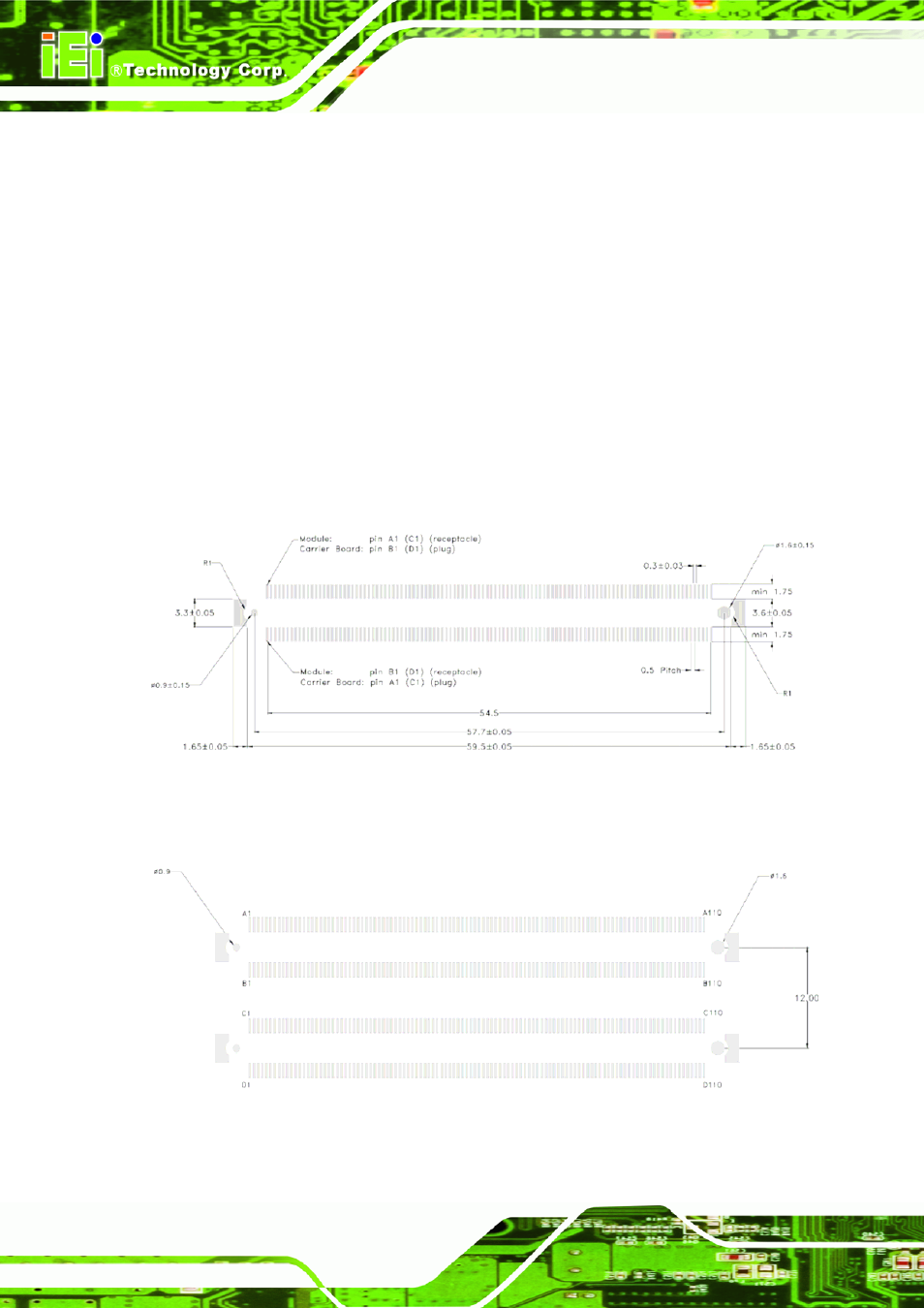
6.3 Connector Footprint
For carrier board designs it is essential that the distance and the alignment of the dual
connector shape on the PCB comply to the dimensions defined by the COM Express
Specification. The alignment between the two single connectors is guaranteed by the
connectors peg holes shown in following drawings. It is very important that the PCB
drill tolerances of these peg holes are within the recommended ranges mentioned
below. Otherwise, the interconnection between module and carrier board may cause
functional problems for the system. Instead of two single connectors, a dual connector
model with a reinforcing bar spacer can be used to ensure the alignment between the
two connectors during assembly. All dimensions of the following drawings are shown
in millimeters or Hirose FX8-100S connector detail spec, please reference the Hirose
website.
Figure 6-3: Single Connector Physical Dimensions
Figure 6-4: Dual Connector Footprint and Alignment