2 pci express slot x1, 3 express card connector, Figure 4-5: pci express x1 slot example – IEI Integration ICE-DB-9S User Manual
Page 53
ICE Module
Page 40
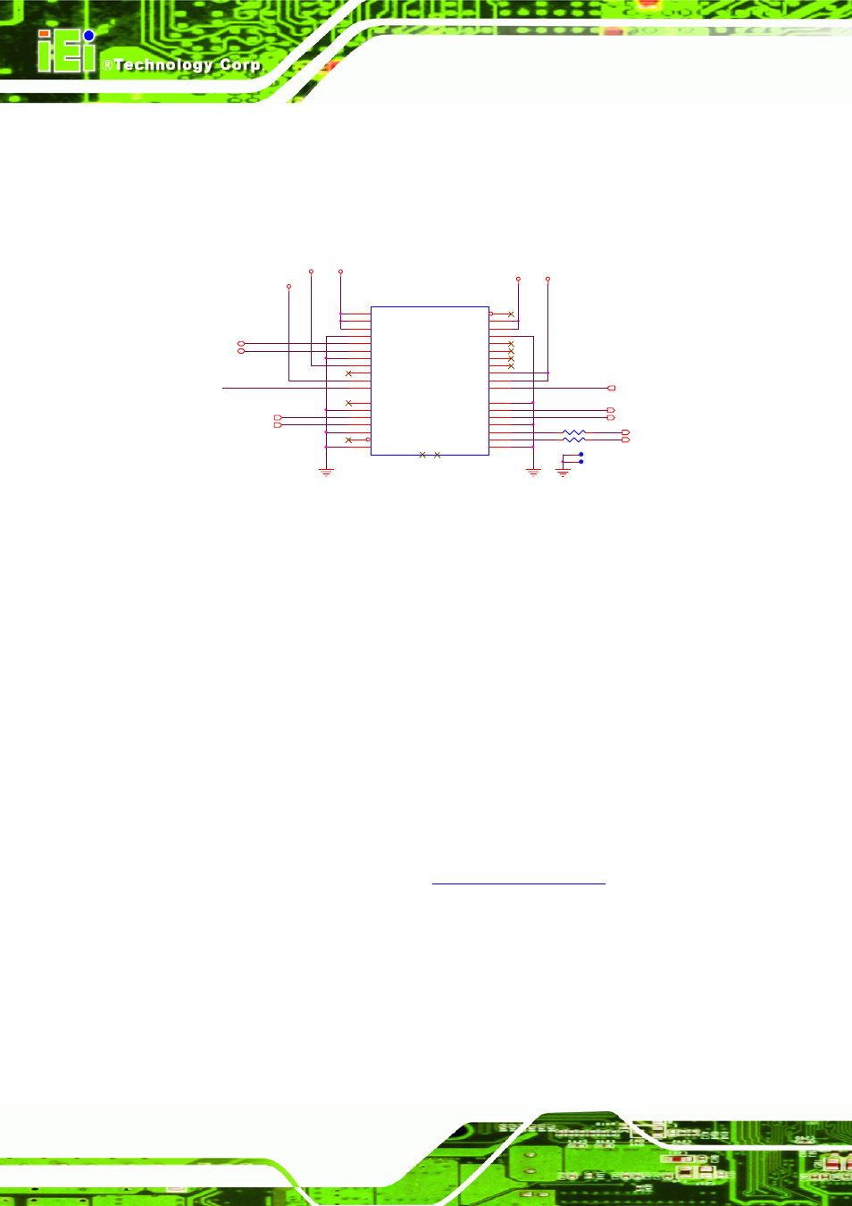
4.2.2 PCI Express Slot X1
Table 4-5 illustrates the pinout definition for the standard x1, x4, x8 and x16 PCI
Express connectors. The dashed lines in the diagram depict where each different
connector type ends. An example of an x1 PCIe slot is shown in Figure 4-5 below.
CB_RESET# 3,6,10,11,14,20
R125
0_4
1
2
+V12
+V3.3
+V3.3_DUAL
PCIE1
PCIE_X1
+12V03
B1
+12V04
B2
RSVD01
B3
GND05
B4
SMBCLK
B5
SMBDATA
B6
GND06
B7
3_3V03
B8
JTAG1
B9
3_3VAUX
B10
WAKE#
B11
PRSNT1#
A1
+12V01
A2
+12V02
A3
GND01
A4
JTAG2
A5
JTAG3
A6
JTAG4
A7
JTAG5
A8
3_3V01
A9
3_3V02
A10
PWRGD
A11
RSVD02
B12
GND07
B13
HSOP0
B14
HSON0
B15
GND08
B16
PRSNT2#
B17
GND09
B18
GND02
A12
REFCLK+
A13
REFCLK-
A14
GND03
A15
HSIP0
A16
HSIN0
A17
GND04
A18
NC1
NC1
NC2
NC2
PCIE_WAKE_UP#
+V3.3
+V12
PCIE_RX1-
3
PCIE_TX1-
3
PCIE_TX1+
3
PCIE_RX1+
3
CLK100M_PCIEx1_SLOT2- 4
CLK100M_PCIEx1_SLOT2+ 4
TP90
1
TP91
1
SMB_DAT
3,4,6,10,11,17,20
SMB_CK
3,4,6,10,11,17,20
R124
0_4
1
2
Figure 4-5: PCI Express x1 Slot Example
4.2.3 Express Card Connector
Hot-swappable Express Cards come in a small form factor and are designed primarily
for mobile computing. The card’s electrical interface is thru USB 2.0 or a single x1
PCIe link. Express Cards are the successor to Card Bus Cards (which are PCI-based).
Card Bus cards, in turn, are the successors to PCMCIA cards. All three formats are
defined by the PCMCIA Consortium.
ExpressCard is a small, modular add-in card designed to replace common PCMCIA
and PC Cards. It takes advantage of the scalable, high-bandwidth serial PCI Express
and USB 2.0 interfaces to provide much higher data rates. COM Express modules
offer support for up to two ExpressCard slots. More information about the
ExpressCard Standard can be found at
In addition to the signals of a PCI Express x1 link and a USB 2.0 link, the ExpressCard
interface requires the following control signals provided by the COM Express module.
The corresponding signals can be found on the module connector rows A and B.