2 giga lan connector, 3 lan link activity and speed led – IEI Integration ICE-DB-9S User Manual
Page 85
ICE Module
Page 72
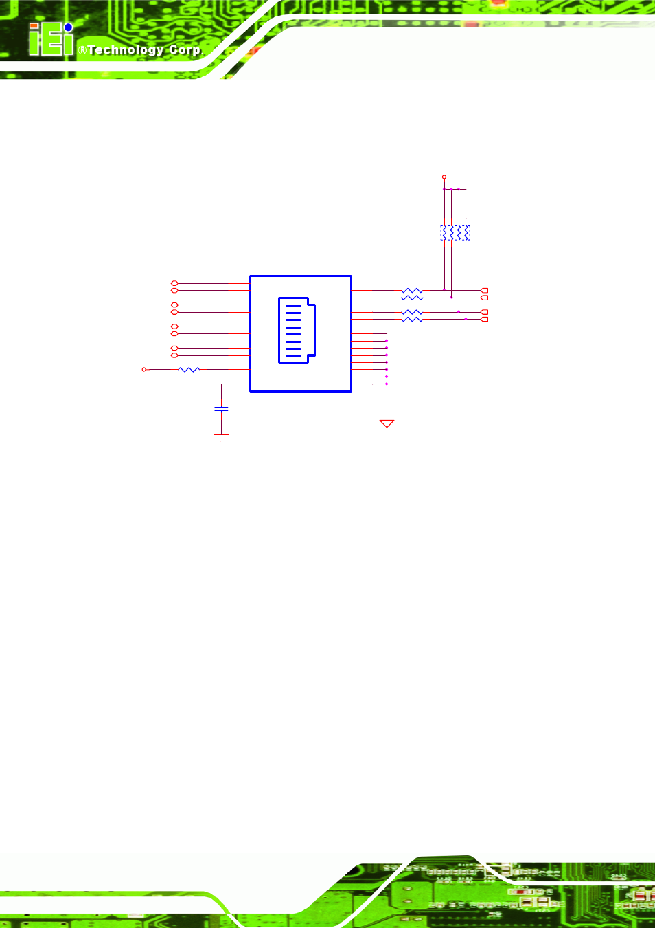
4.11.2 Giga LAN Connector
IEI uses the RJ-45 connector including the transformer.
R230
0_4
R231
220_4
GBE0_MDI1+
3
IO_GND
R232
0_4
C187
0.1U_4_Y_16V
R233
0_4
GREEN
YELLOW
LAN_USB1A
LJ-G40BU1-10
CT1
P1
MD3-
P9
MD2+
P6
MD2-
P7
LEFT-P
P14
LEFT-N
P13
RIGHT-P
P12
RIGHT-N
P11
MD3+
P8
GND
P10
MD0+
P2
MD0-
P3
MD1-
P5
MD1+
P4
FG1
15
FG2
16
PG3
9
FG4
10
FG5
11
FG6
12
FG7
13
FG8
14
GBE0_LINK# 3
+V1.8_LAN
GBE0_MDI2-
3
GBE0_MDI2+
3
GBE0_MDI0-
3
GBE0_MDI0+
3
GBE0_MDI1-
3
GBE0_MDI3-
3
GBE0_MDI3+
3
+V3.3_DUAL
GBE0_LINK1000# 3
R229
220_4
RN28
330_8P4R04
1
3
5
7
2
4
6
8
GBE0_ACT#
3
GBE0_LINK100# 3
Figure 4-33: Giga Lan Connection Exampel (including Transformer)
4.11.3 LAN Link Activity and Speed LED
The COM Express module has four 3.3V open drain outputs to directly drive activity,
speed indication and link status LEDs. The 3.3V standby voltage should be used as
LED supply voltage so that the link activity can be viewed during system standby state.
Since LEDs are likely to be integrated into a RJ-45 connector with integrated
magnetics module, the LED traces need to be routed away from potential sources of
EMI noise.