1 four-layer stack-up, 2 six-layer stack-up, Figure 5-1: four layers stack – IEI Integration ICE-DB-9S User Manual
Page 101
ICE Module
Page 88
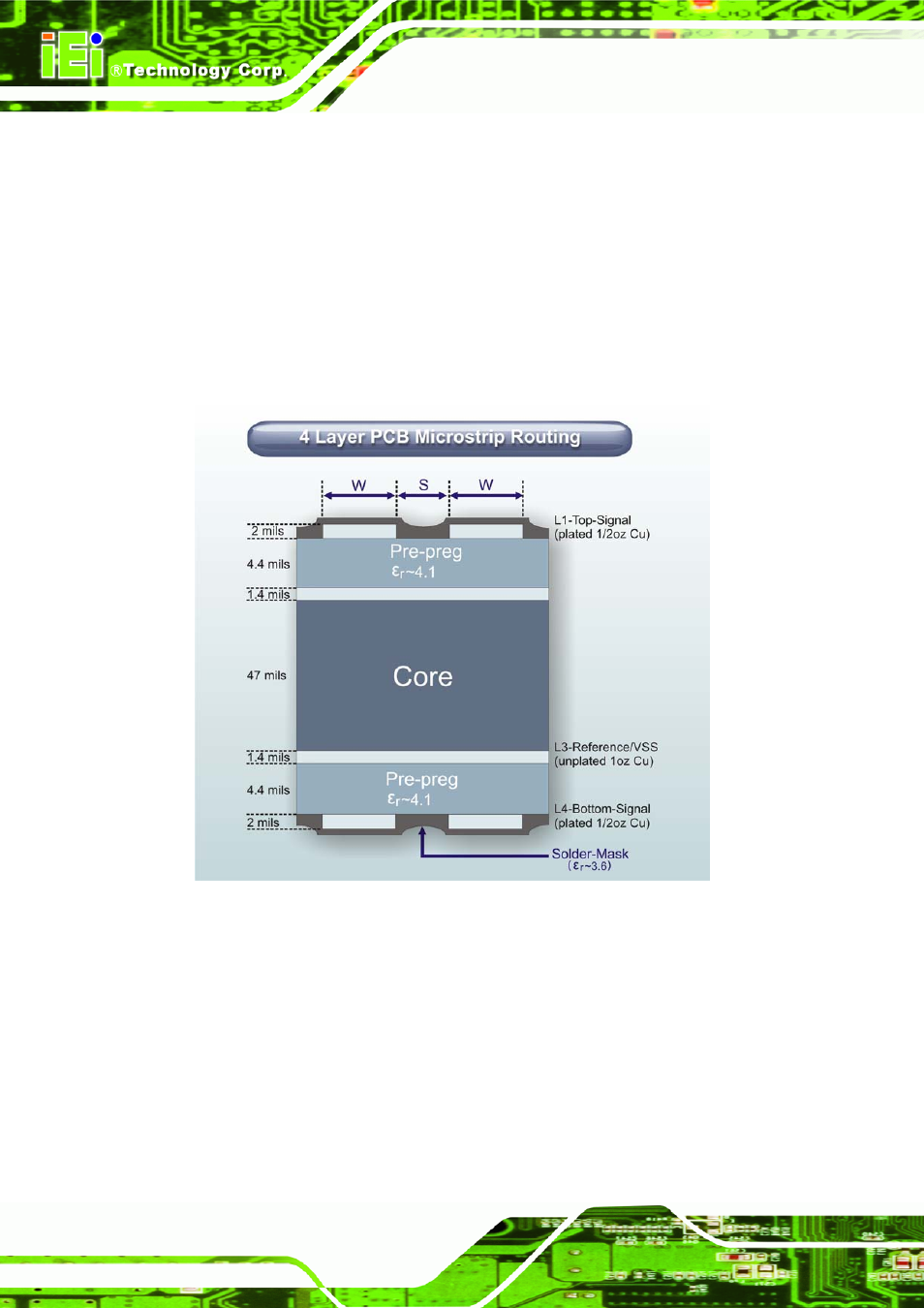
5.3.1 Four-Layer Stack-up
Figure 5-1 below is an example of a four layer stack-up. Layers L1 and L4 are used for
signal routing. Layers L2 and L3 are used for solid ground and power planes
respectively. Microstrips on Layers 1 and 4 reference ground and power planes on
Layers 2 and 3 respectively. In some cases, it may be advantageous to swap the GND
and PWR planes. This allows Layer 4 to be GND referenced. Layer 4 is clear of parts
and may be the preferred primary routing layer.
Figure 5-1: Four Layers Stack
5.3.2 Six-Layer Stack-up
Figure 5-2 below is an example of a six layer stack-up. Layers L1, L3, L4 and L6 are
used for signal-routing. Layers L2 and L5 are power and ground planes respectively.
Microstrips on Layers 1 and 6 reference solid ground and power planes on Layers 2
and 5 respectively. Inner Layers 3 and 4 are asymmetric striplines that are referenced
to planes on Layers 2 and 5.
- SPCIE-5100DX (180 pages)
- SPCIE-C2060 v1.01 (200 pages)
- SPCIE-C2060 v2.12 (212 pages)
- SPCIE-C2160 (204 pages)
- SPCIE-C2260-i2 (217 pages)
- ROCKY-3786 v4.0 (175 pages)
- ROCKY-3786 v4.10 (147 pages)
- PCIE-Q350 v1.00 (272 pages)
- PCIE-Q350 v1.12 (250 pages)
- PCIE-Q350 v1.20 (250 pages)
- PCIE-Q350 v1.30 (213 pages)
- PCIE-Q57A (159 pages)
- PCIE-G41A2 (151 pages)
- PCIE-Q670 v1.03 (206 pages)
- PCIE-Q670 v2.00 (205 pages)
- PCIE-H610 (181 pages)
- PCIE-Q870-i2 (217 pages)
- IOWA-LX-600 (159 pages)
- PCISA-945GSE v1.01 (207 pages)
- PCISA-945GSE v1.10 (190 pages)
- PCISA-9652 v1.00 (232 pages)
- PCISA-9652 v1.01 (232 pages)
- PCISA-PV-D4251_N4551_D5251 (145 pages)
- PICOe-945GSE (197 pages)
- PICOe-GM45A (198 pages)
- PICOe-PV-D4251_N4551_D5251 v1.00 (154 pages)
- PICOe-PV-D4251_N4551_D5251 v1.10 (154 pages)
- PICOe-PV-D4251_N4551_D5251 v1.11 (155 pages)
- PICOe-B650 (156 pages)
- PICOe-HM650 (174 pages)
- HYPER-KBN (139 pages)
- SPXE-14S (3 pages)
- SPXE-9S v1.00 (5 pages)
- SPXE-9S v1.1 (6 pages)
- SPE-9S v1.00 (4 pages)
- SPE-9S v1.1 (5 pages)
- SPE-6S (3 pages)
- SPE-4S (4 pages)
- PE-6SD3 (4 pages)
- PE-6SD2 v4.0 (4 pages)
- PE-6SD2 v2.10 (3 pages)
- PE-6SD (3 pages)
- PE-6S3 v1.0 (2 pages)
- PE-6S3 v4.0 (4 pages)
- PE-6S2 (4 pages)