13 vga, 1 signal description, 1 hsync and vsync signals – IEI Integration ICE-DB-9S User Manual
Page 92: 2 esd, 3 ddc interface, 2 vga connector, 3 vga dac filter, 4 routing guide line, Figure 4-40: ir reference schematic, Table 4-23: vga signals description
Page 79
ICE Module
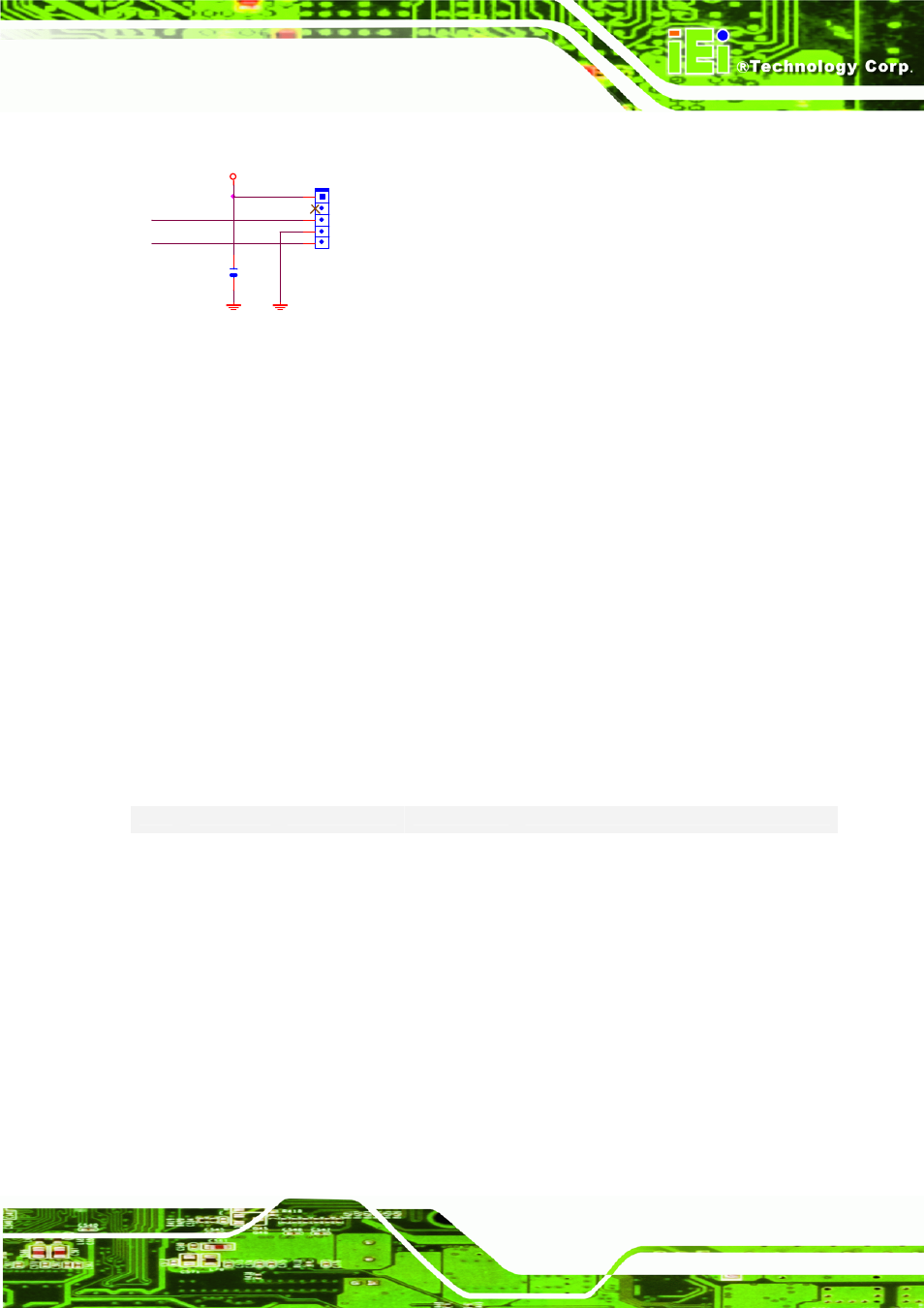
+V5
UART_TX2
UART_RX2
IR CONNECTOR
IR1
IR_5X1_2.54
1
3
4
5
2
C260
0.1U_4_Y_16V
Figure 4-40: IR Reference Schematic
4.13 VGA
COM Express provides analog display signals. There are three signals -- red, green,
and blue -- that send color information to a VGA monitor. These three signals each
drive an electron gun that emits electrons which paint one primary color at a point on
the monitor screen. Analog levels between 0 (completely dark) and 0.7 V (maximum
brightness) on these control lines tell the monitor what intensities of these three
primary colors to combine to make the color of a dot (or pixel) on the monitor’s screen.
4.13.1 Signal Description
Table 4-23 shows COM Express VGA signals, including pin number, signals, I/0,
power plane, terminal resistors, damping resistors and descriptions.
Table 4-23: VGA signals description
Pin
D-SUB15
Signal
I/O
Description
B89 1
VGA_RED
O Analog
Red component of analog DAC monitor
output, designed to drive a 37.5Ω equivalent
load.
B91 2
VGA_GRN
O Analog
Green component of analog DAC monitor
output, designed to drive a 37.5Ω equivalent
load.
B92 3
VGA_BLU
O Analog
Blue component of analog DAC monitor
output, designed to drive a 37.5Ω equivalent
load.
B93 13
VGA_HSYNC
O 3.3V
CMOS
Horizontal sync output to VGA monitor.
B94 14
VGA_VSYNC O 3.3V
CMOS
Vertical sync output to VGA monitor.
B95 15
VGA_I2C_CK
I/O 3.3V
CMOS
DDC clock line (I2C port dedicated to
identify VGA monitor capabilities). DDC data
line.
B96
VGA_I2C_DAT I/O 3.3V
CMOS
DDC clock line (I2C port dedicated to
identify VGA monitor capabilities). DDC data