IEI Integration ICE-DB-9S User Manual
Page 114
Page 101
ICE Module
One version has threaded standoffs and the other has non-threaded standoffs (bore
hole). The following sections describe these two common mounting possibilities and
the additional components (standoffs, screws, etc...) that are necessary to implement
the respective solution.
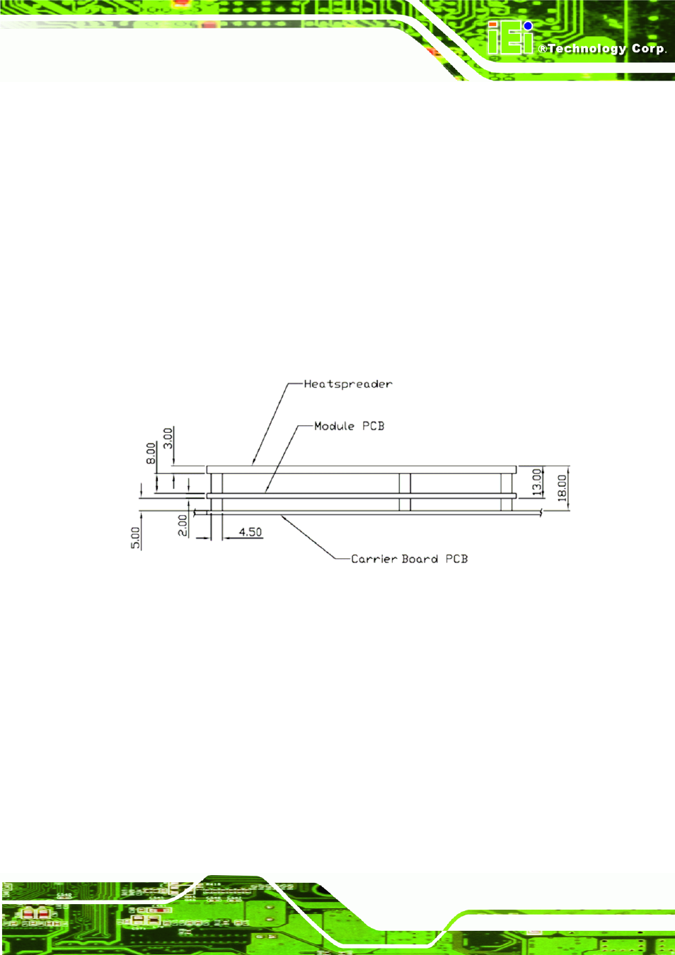
Modules should be equipped with a heat-spreader. This heat-spreader by it self does
not constitute the complete thermal solution for a module but provides a common
interface between modules and implementation-specific thermal solutions. The overall
module height from the bottom surface of the module board to the heat-spreader top
surface shall be 13 mm for both the Basic and Extended Modules. The module PCB
and heat-spreader plate thickness are vendor implementation specific, however, a
2-mm PCB with a 3-mm heat-spreader may be used which allows use of readily
available standoffs.
Figure 6-6: Overall Height for Heat-Spreader in Basic and Extended Modules
All dimensions in mm. Tolerances (unless otherwise specified): Z (height) dimensions
should be ± 0.8mm [±0.031”] from top of Carrier Board to top of heat-spreader.
Heat-spreader surface should be flat within 0.2mm [.008"] after assembly. Interface
surface finish should have a maximum roughness average (Ra) of 1.6μm [63μin]. The
critical dimension in Figure 6-8 is the module PCB bottom side to heat-spreader top
side. This dimension shall be 13.00mm ± 0.65mm [±0.026”]. Figure 6-8 shows a cross
section of a module and heat-spreader assembled to a Carrier Board using the 5mm
stack height option. If 8mm Carrier Board connectors are used, the overall assembly
height increases from 18.00mm to 21.00mm.