3 esd protection, 4 reference schematic, Figure 4-32: tv out schematic reference – IEI Integration ICE-DB-9S User Manual
Page 83
ICE Module
Page 70
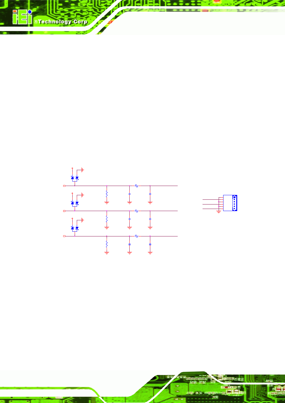
4.10.2.3 ESD Protection
ESD clamp diodes are required for each TV-DAC channel. These low capacitance
clamp diodes should be placed as near as possible to the TV-Out connector on the
COM Express carrier board between +5V supply voltage and ground.
4.10.2.4 Reference Schematic
At least 30 mils of spacing should be used for the routing between each TV-DAC
channel to prevent crosstalk between the TV-DAC signals. The maximum trace length
distance of the TV-DAC signals between the COM Express connector and the 150Ω
±1% termination resistor should be within 12 inches. This distance should be routed
with a 50 Ω trace impedance.
TV_DAC_C
3
TV_DAC_B
3
TV_DAC_A
3
TV_AGREEN_Y
C133
3.3P_4_N_50V
2
1
TV_ABLUE_CVBS
C132
3.3P_4_N_50V
2
1
R168
150_4_1%
L9
FB150_6_200MA
+V3.3
D7
BAV99LT1G_SOT23
A
C
K
C129
3.3P_4_N_50V
2
1
+V3.3
D8
BAV99LT1G_SOT23
A
C
K
C128
3.3P_4_N_50V
2
1
R169
150_4_1%
TV_ARED_C
R170
150_4_1%
+V3.3
L10
FB150_6_200MA
D6
BAV99LT1G_SOT23
A
C
K
L11
FB150_6_200MA
C131
3.3P_4_N_50V
2
1
C130
3.3P_4_N_50V
2
1
TV_ABLUE_CVBS
TV_AGREEN_Y
TV_ARED_C
TV1
HEADER_2X3_2.54
GND
1
Y
2
GND
3
C
4
GND
5
CVBS
6
Figure 4-32: TV Out Schematic Reference