4 over current protection, 5 reference schematics – IEI Integration ICE-DB-9S User Manual
Page 71
ICE Module
Page 58
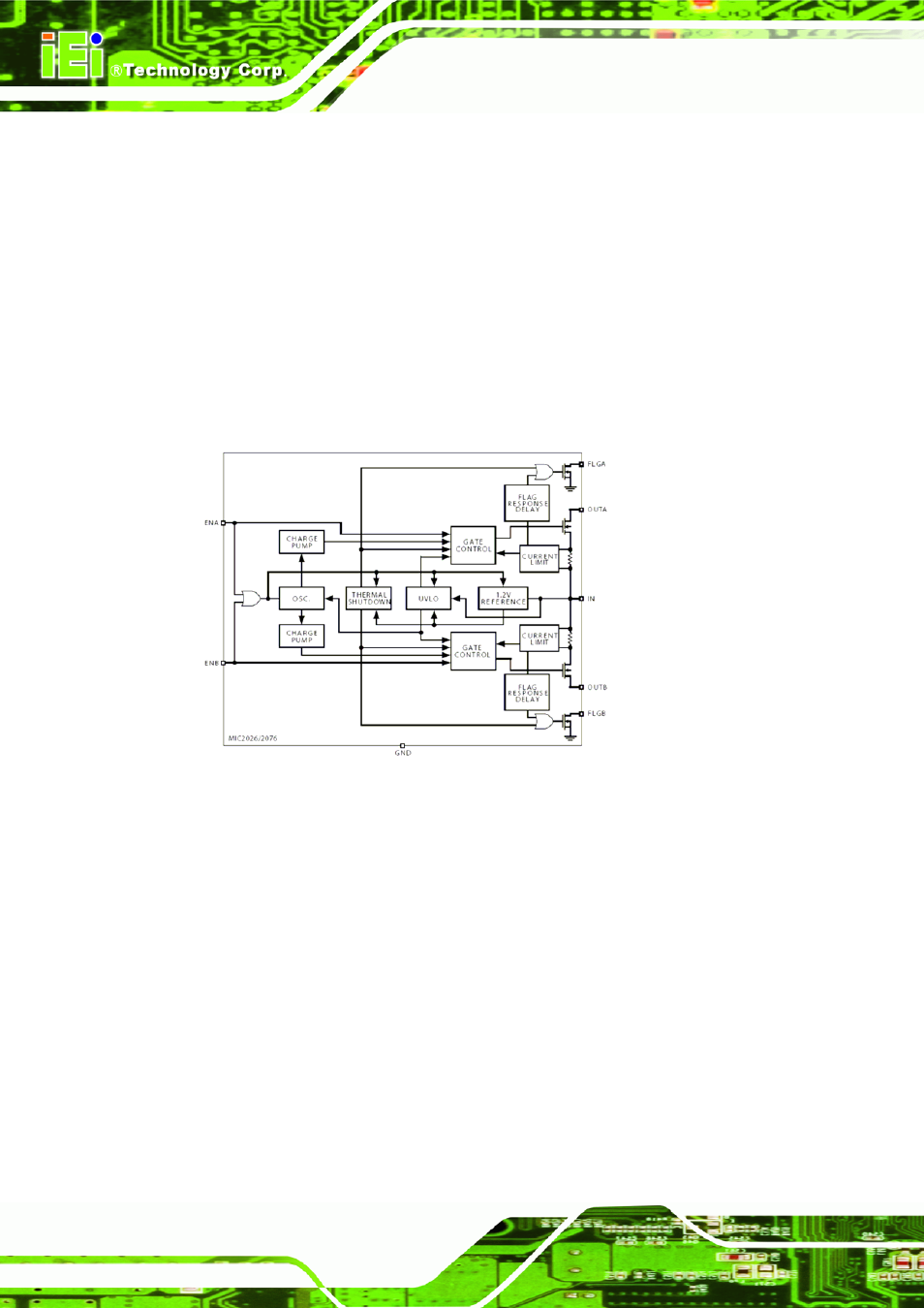
4.5.4 Over Current Protection
Over-current protection for USB ports can be implemented by using power distribution
switches on the carrier board that monitor the USB port power lines. Power distribution
switches usually have a soft-start circuitry that minimizes inrush current in applications
where highly capacitive loads are employed. Transient faults are internally filtered.
Additionally, they offer a fault status output that is asserted during over-current and
thermal shutdown conditions. These outputs should be connected to the
corresponding COM Express modules USB over-current sense signals. IEI uses
MIC2026 for carrier board.
Figure 4-23: MIC2026 Block Diagram(Please refer the datasheet from MICREL )
4.5.5 Reference Schematics
The following notes apply to Figure 4-24 below.
LAN_USB and CN26 incorporate two USB Type A receptacles, LAN_USB in addition
includes an RJ-45 (LANKom LJ -G40BU1-10-F).
The reference design uses an over-current detection and protection device. The Micrel
MIC2026 is dual channel power distribution switch. Power to the USB Port is filtered
using a ferrite (30 Ω @100MHz, 600mA) to minimize emissions. The ferrite should be
placed adjacent to the USB Port connector pins. The OC# signal is asserted until the
over-current or over-temperature condition is resolved.