3 signal table terminology, Ignal, Able – IEI Integration ICE-DB-9S User Manual
Page 36: Erminology, Table 3-2: conventions and terminology
Page 23
ICE Module
3.3 Signal Table Terminology
The following section describes the signals found on COM Express Type 2 connectors.
Most of the signals listed in the following sections also apply to other COM Express
module types. The pinout for connector rows A and B remains the same regardless of
the module type but the pinout for connector rows D and C are dependent on the
module type. Refer to the COM Express specification for information about the
different pin-outs of the module types other than Type 2.
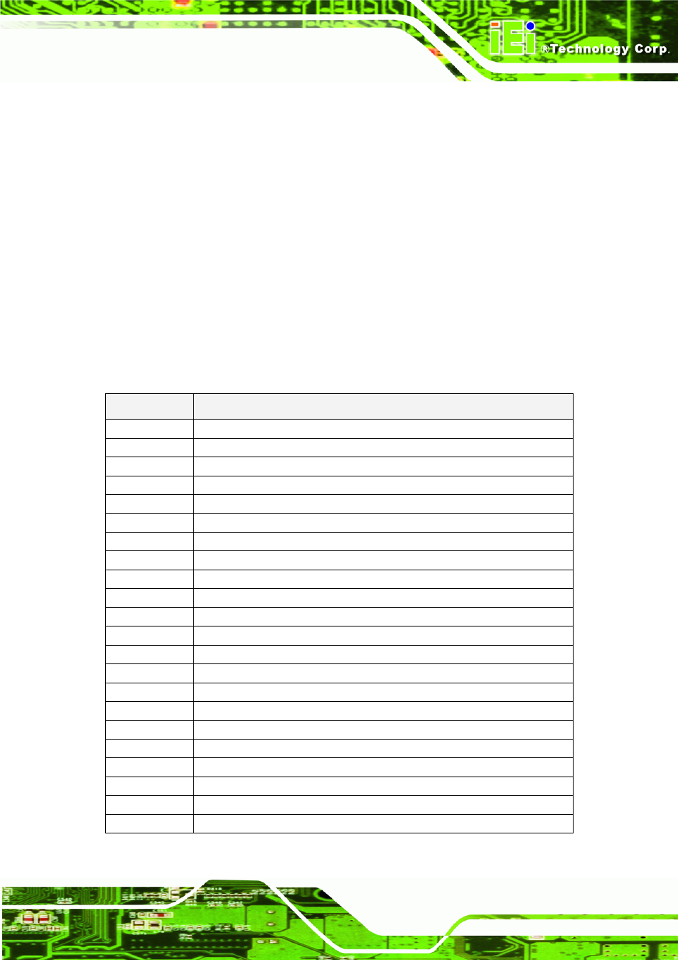
Table 3-2 below describes the terminology used in this section for the Signal
Description tables. The “#” symbol at the end of the signal name indicates that the
active or asserted state occurs when the signal is at a low voltage level. When “#” is
not present, the signal is asserted when at a high voltage level.
Table 3-2: Conventions and Terminology
Term
Description
I/O
Bi-directional signal
I
Input signal
O
Output signal
I/F
Interface
GND Ground
PWR Power
OD
Open drain output
PD Pull
down
PU Pull
up
+V12
+12V ±5% Volts Normal Power
+V5SB
+5V ±5% Standby Power
+3.3VSB
+3.3V ±5% Standby Power
+V3.3
+3.3V ±5% Volts Normal Power
+V5
+5V ±5% Volts Normal Power
# Active-Low
Signals
‘+’ and ‘-‘
Differential Pairs
PM Power
Management
GBE
Giga Bits Ethernet