2 usb keyed connector protocol – IEI Integration ICE-DB-9S User Manual
Page 68
Page 55
ICE Module
B37
B36
USB7+
USB7-
I/O
USB Differential Data Port 7.
B44 USB_0_1_OC# I 3.3V CMOS
USB over-current sense, USB ports 0 and 1. A pull-up for this
line shall be present on the module. An open drain driver from
a USB current monitor on the Carrier Board may drive this
line low. Do not pull this line high on the Carrier Board.
A44 USB_2_3_OC# I 3.3V CMOS
USB over-current sense, USB ports 2 and3. A pull-up for this
line shall be present on the module. An open drain driver from
a USB current monitor on the Carrier Board may drive this
line low. Do not pull this line high on the Carrier Board.
B38 USB_4_5_OC# I 3.3V CMOS
USB over-current sense, USB ports 4 and 5. A pull-up for this
line shall be present on the module. An open drain driver from
a USB current monitor on the Carrier Board may drive this
line low. Do not pull this line high on the Carrier Board.
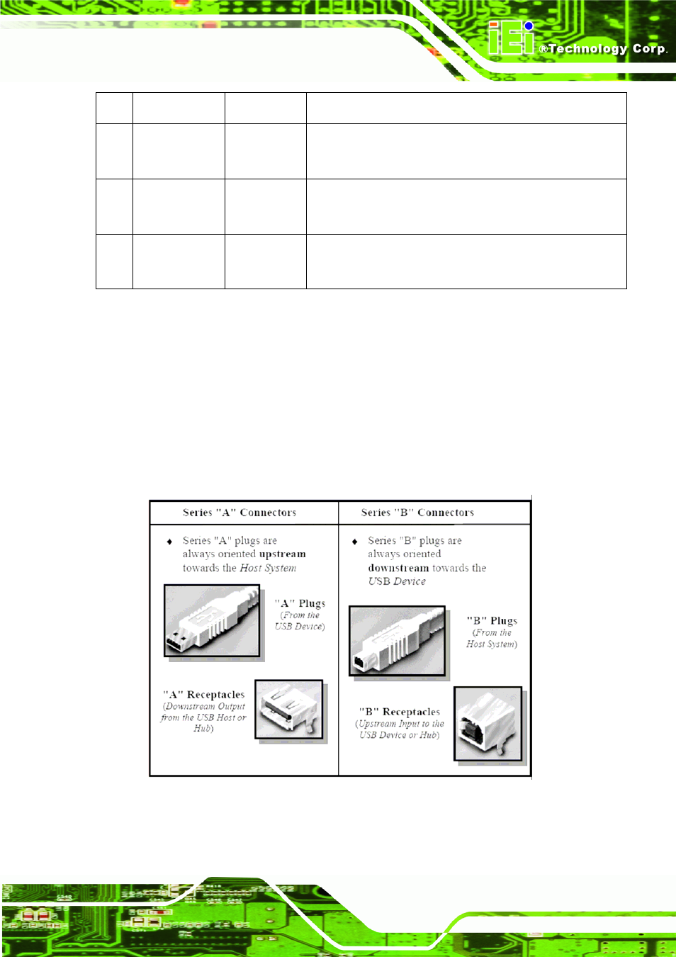
4.5.2 USB Keyed Connector Protocol
To minimize end user termination problems, USB uses a “keyed connector” protocol.
The physical difference in the Series “A” and “B” connectors insures proper end user
connectivity. The “A” connector is the principle means of connecting USB devices
directly to a host or to the downstream port of a hub. All USB devices must have the
standard Series “A” connector specified in this chapter. The “B” connector allows
device vendors to provide a standard detachable cable. This facilitates end user cable
replacement.
Figure 4-19: Keyed Connector Protocol (Refer to USB2.0 Spec.)