3 sata led, 4 sata routing guideline, Figure 4-18: sata led connection example – IEI Integration ICE-DB-9S User Manual
Page 66: Table 4-12: sata impedance consideration
Page 53
ICE Module
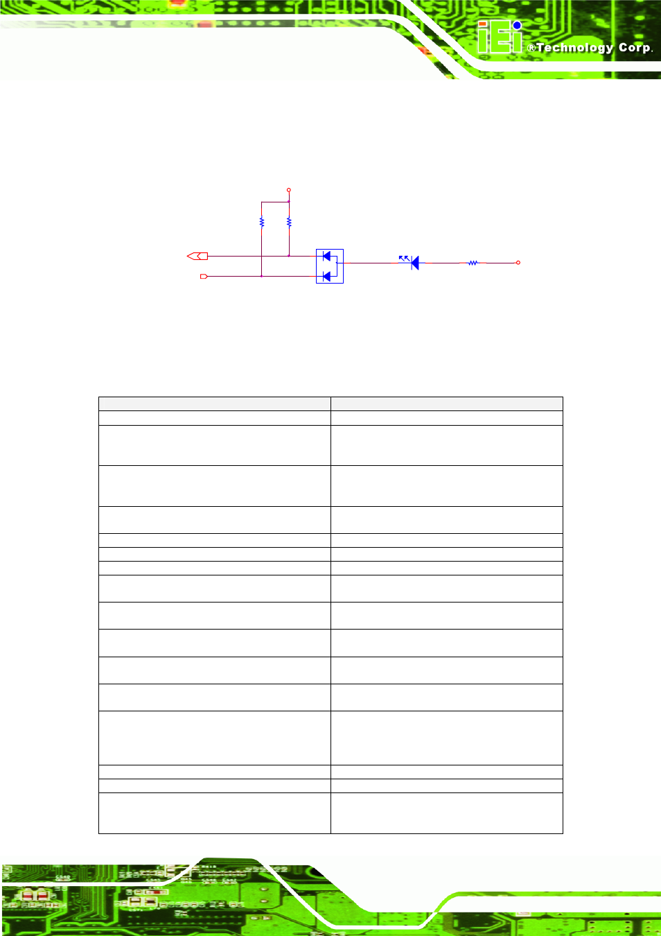
4.4.3 SATA LED#
The SATA LED can be used with the HDD LED. Please refer to the following
schematic diagram.
+V3.3
ATA_ACT#
3,21
HDD_LED#
11,21
R324
470_6_5%
+V5
D17
BAW56LT1_SOT23
1
K1
3
C
2
K2
LED1
LEDRED_8_2
A
C
R322
4.7K
R323
4.7K
HDD_LED#
Figure 4-18: SATA LED Connection Example
4.4.4 SATA Routing Guideline
Table 4-12: SATA Impedance Consideration
Parameters
Routing
Transfer Rate
3.0 Gbits/sec
Maximum signal line length (coupled traces)
7.0 inches on PCB (COM Express module
and carrier board. The length of the SATA
cable is specified between 0 and 40 inches) "
Signal length used on COM Express module
(including the COM Express" carrier board
connector) "
2.5 inches
Signal length available for the COM Express
carrier board "
4.5 inches
Differential Impedance
100 Ohms +/-20%
Single-ended Impedance
55 Ohms +/-15%
Trace width (W)
5mils (microstrip routing) (*)
Spacing between differential pairs (intra-pair)
(S)
7mils (microstrip routing) (*)
Spacing between RX and TX pairs
(inter-pair) (s)
Min. 20mils
Spacing between differential pairs and
high-speed periodic signals
Min. 50mils
Spacing between differential pairs and
low-speed non periodic signals
Min. 20mils
Length matching between differential pairs
(intra-pair)
Max. 5mils
Length matching between RX and TX pairs
(inter-pair)
No strict electrical requirements. Keep
difference within a 3.0 inch delta to minimize
latency. Do not serpentine to meet trace
length guidelines for the RX and TX path.
Spacing from edge of plane
Min. 40mils
Via Usage
Try to minimize number of vias
AC Coupling capacitors
The AC coupling capacitors for the TX and
RX lines are incorporated on the COM
Express module. "