1 atx power status (s0,s3,s4,s5,g3), Table 5-1: signal tables terminology descriptions, Table 5-2: power state behavior – IEI Integration ICE-DB-9S User Manual
Page 104
Page 91
ICE Module
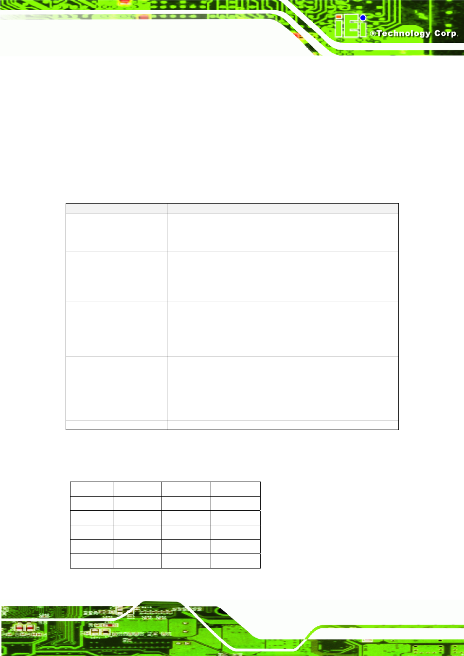
5.4.1 ATX Power Status (S0,S3,S4,S5,G3)
ATX power source will provide 12V , -12V , 5V , -5V , 3.3V , 5VSBY power , if other
voltage is required (3.3VSBY , LAN1.8V…. ) on carried board. The additional
switching regulator or LDO will be necessary. Power states are described by the
following terms:
Table 5-1: Signal Tables Terminology Descriptions
State
Description
Comment
G3
Mechanical Off
AC power to system is removed, by a mechanical switch. System
power consumption is near zero – the only power consumption is
that of the RTC circuits powered by a backup battery.
S5
Soft Off
System is off except for a small subset that is powered by the 5V
suspend rail. There is no system context preserved.
VCC_5V_SBY current consumption is system dependent, and it
may be from tens of milliamps up to several hundred milliamps.
S4
Suspend to Disk
System is off except for a small subset that is powered by the 5V
suspend rail. System context is preserved on a non-volatile disk
media (that is powered off). VCC_5V_SBY current consumption
is system dependent, and it may be from tens of milliamps up to
several hundred milliamps.
S3
Suspend to RAM
System is off except for system subset that includes the RAM.
Suspend power is provided by the 5V suspend rail. System
context is preserved in the RAM. VCC_5V_SBY current
consumption is system dependent, and it may be from several
hundred milliamps up to a maximum of 2A.
S0
On
System is on.
Table 5-2: Power State Behavior
State SUS_S5#
SUS_S4#
SUS_S3#
G3
N/A N/A N/A
S5
Low Low Low
S4
High Low Low
S3
High High Low
S0
High High High