4 sata (serial ata interface), 1 signal description, 4 sata – IEI Integration ICE-DB-9S User Manual
Page 64: Erial, Ata i, Nterface, Table 4-10: pci impedance consideration
Page 51
ICE Module
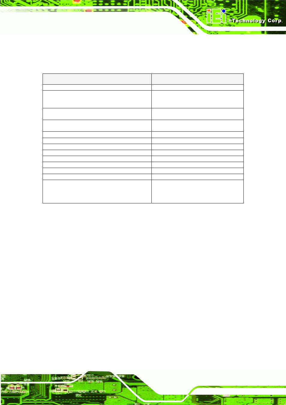
signal traces. Refer to section 8.1 'PCI Trace Routing Guidelines' and the 'PCI Local
Bus Specification Revision 2.3' to get more information about this subject.
Table 4-10: PCI Impedance Consideration
Parameters
Routing
Transfer Rate @ 33MHz
132 MB/sec
Signal length used on COM Express module
(including the COM Express" carrier board
connector) "
3.0 inches
Maximum data and control signal length
allowance for the COM Express carrier board. "
10 inches
Maximum clock signal length allowance for the
COM Express carrier board. "
8.88 inches
Single-ended Impedance
55 Ohms +/-15%
Trace width (W)
5mils (microstrip routing) (*)
Spacing between signals (inter-signal) (S)
7mils (microstrip routing) (*)
Length matching between single ended signals
Max. 200mils
Length matching between clock signals
Max. 200mils
Spacing from edge of plane
Min. 40mils
Reference plain
GND referenced preferred
Via Usage
Try to minimize number of vias
Decoupling capacitors for each PCI slot.
Min. 1x22μF, 2x 100nF @ VCC 5V Min.
2x22μF, 4x 100nF @ VCC 3.3V Min.
1x22μF, 2x 100nF @ +12V (if used) Min.
1x22μF, 2x 100nF @ -12V (if used)
4.4 SATA (Serial ATA Interface)
Serial ATA is a serial interface for connecting storage devices (mainly hard disks) and
was defined to replace the old parallel ATA interface. SATA uses a point-to-point serial
connection between the system and the storage device. The first generation of
standard SATA provides a maximum effective data transfer rate of 150 MB/s per port.
With the second generation SATA II, an effective transfer rate of up to 300 MB/s per
port is possible. Serial ATA is completely software transparent to the IDE interface
while providing a lower pin count and higher performance.
4.4.1 Signal Description
All COM Express modules provide up to 4 Serial ATA channels, each with a receive
and transmit differential signal pair designated from 'SATA0_RX' (+ and -) to
'SATA3_RX'
(+ and -) and correspondingly from 'SATA0_TX' (+ and -) to 'SATA3_TX'
(+ and -). The appropriate signals can be found on the COM Express module
connector row A and row B.