2 lvds cable consideration, 3 backlight and lcd power timing control, Figure 4-25: lvds power control – IEI Integration ICE-DB-9S User Manual
Page 75: Lvds
ICE Module
Page 62
4.6.2 LVDS Cable Consideration
Balanced cables (twisted pair) are usually better than unbalanced cables (ribbon cable)
for noise reduction and signal quality. Balanced cables tend to generate less EMI due
to field canceling effects and also tend to pick up electromagnetic radiation as
common-mode noise, which is rejected by the receiver. Twisted pair cables provide a
low-cost solution with good balance and flexibility. They are capable of medium to long
runs depending upon the application skew budget. A variety of shielding options are
available.
Ribbon cables are a cost effective and easy solution. Even though they are not well
suited for high-speed differential signaling they do work fine for very short runs. Most
cables will work effectively for cable distances of <0.5m.
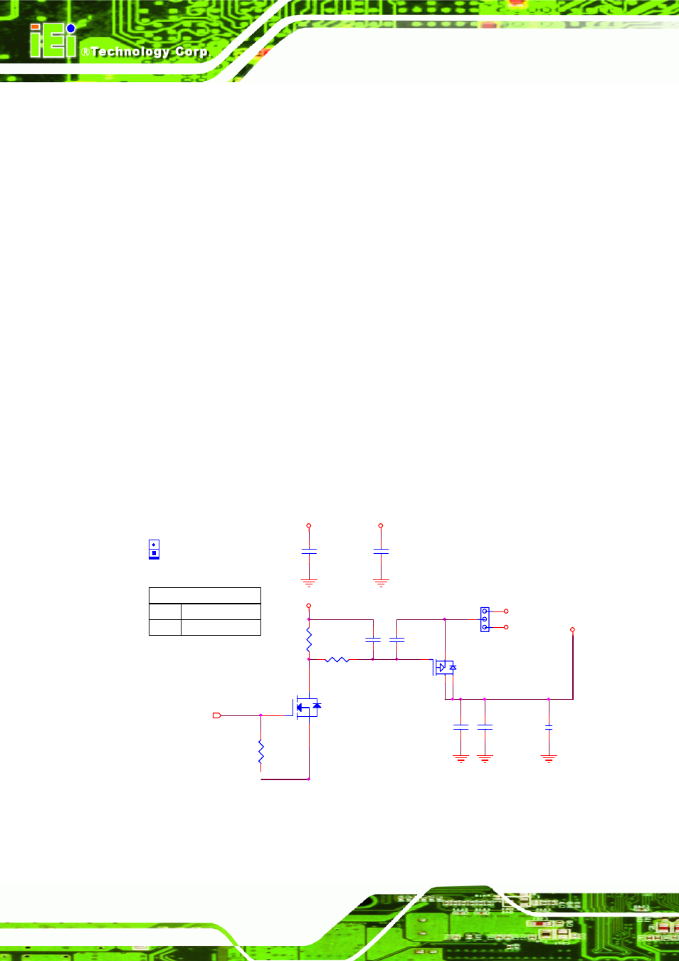
4.6.3 Backlight and LCD Power Timing Control
Figure 4-25 is a reference design of backlight and LCD power timing control. In Figure
4-26, VIN is LCD power and lamp is LCD backlight power. Figure 4-27 shows the LCD
power sequence, and design must conform to it’s power sequence.
LVDS_VDD_EN
3
C269
1000P_4_X_50V
LVDS
C273
2.2U_6_Y_10V
1
2
C272
10U_1210_Y_25V
2
1
5V
3.3V(Default)
2-3
1-2
J_VLVDS1
J_VLVDS1(1-2)
MINIJUMPER_1X2_2
Q2A
FDS6975_SOP8
2
1
7 8
R145
1M_4
1
2
+V12
+V3.3_LCD_PANEL
Q3
2N7002_SOT23
D
G
S
G
D
R151
100K_4
1
2
S
+V3.3
+V5
J_VLVDS1
HEADER_1X3_2
1
2
3
C110
10U_8_X_6V3
C109
10U_8_X_6V3
+V3.3
C270
0.1U_4_Y_16V
C271
0.1U_4_Y_16V
R417
100K_4
1
2
+V5
Figure 4-25: LVDS Power Control