3) list of pio signal functions – IAI America PSEP User Manual
Page 40
34
/
2.
Wiring
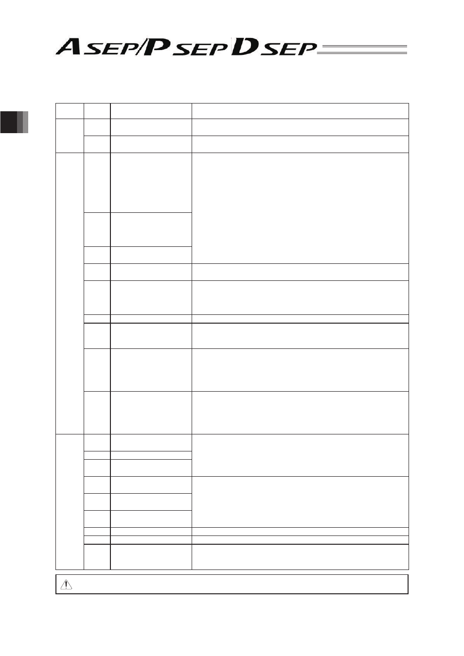
(3) List of PIO Signal Functions
Signal
Type
Symbol
Signal Name
Function
Power
Input
24V
I/O Power Supply
It is the common power source for I/O circuit. The positive (
) side of 24V
DC is connected.
0V
I/O Power Supply
It is the common power source for I/O circuit. The positive (
) side of 24V
DC is connected.
Input
ST0
• Movement Signal
[Single Solenoid System]
• Backward Position
Movement Signal
[Double Solenoid System]
• Movement Signal 1
[PIO Pattern 3]
The positioning to the corresponding target position is performed, when the
signal leading edge created in the mode change from OFF to ON, or ON
level is detected.
ST1
• Forward Position
Movement Signal
• Movement Signal 2
[PIO Pattern 3]
ST2
Intermediate Position
Movement Signal
*STP
Pause Signal
When this signal is turned OFF the deceleration is stopped. When the signal
is turned ON again, the movement is re-started.
RES
Reset Signal
When the signal leading edge created in the mode change from OFF to ON,
is detected, the currently issued alarm is reset.
* Depending on the alarm level, alarm reset might not be available.
Refer to the Trouble Shooting for the details.
SON
Servo ON Signal
During the time when this signal is turned ON, the servo-motor is in the ON mode.
SPDC
Movement Speed Change
Signal
When the movement speed is changed during the movement, do it with this
signal turned ON.
* This signal is effective when the PIO pattern 1 has been set.
CN1
Target Position Change
Signal
When the conditions for the positioning operation or pressing operation, etc.,
are changed to operate the system, turn ON this signal.
When this signal is turned ON or OFF during the operation, the position data
is changed.
* This signal is effective when the PIO pattern 2 has been set.
ASTR
Continuous Reciprocating
Operation Signal
During the time when this signal is turned ON, the actuator’s continuous
reciprocating operation is performed between the forward position and the
backward position. When this signal is turned OFF during the movement
operation, after the actuator is positioned to the current target, it is stopped.
* This signal is effective when the PIO pattern 5 has been set.
Output
LS0
Backward Position
Detection
The same operation as of the limit switch of the air cylinder is performed.
It is turned ON when the current position is within the positioning width for
each position detection output.
LS1
Forward Position Detection
LS2
Intermediate Position
Detection
PE0
Backward Positioning
Completion
This signal is turned ON when the current position goes within the position-
ing width, and the positioning to the target position is complete.
It is turned OFF in the Servo-Motor OFF mode or the Emergency Stop
Mode.
PE1
Forward Positioning
Completion
PE2
Intermediate Positioning
Completion
HEND
Home Return Completion
This signal is turned ON when the home return operation is completed.
SV
Servo ON Signal
This signal is turned ON when the servo-motor is turned ON and driving is enabled.
*ALM
Alarm Output Signal
This signal is turned ON when the controller is in the normal condition and
turned OFF when the controller is in the alarm condition. In such case,
monitor this signal in the PLC and take an appropriate measure.
Note For the PLC Input signal, keep it ON for at least 7ms or more.